
Method and apparatus to change the operating frequency of system core logic to maximize system memory bandwidth

a technology of system core logic and operating frequency, applied in the field of data processing system, can solve the problems of increasing the possibility of system crash, complicated setting of this frequency, and hazardous dynamic switching of the core frequency

Inactive Publication Date: 2005-07-28
IBM CORP
View PDF4 Cites 51 Cited by
  • Summary
  • Abstract
  • Description
  • Claims
  • Application Information

AI Technical Summary

Benefits of technology

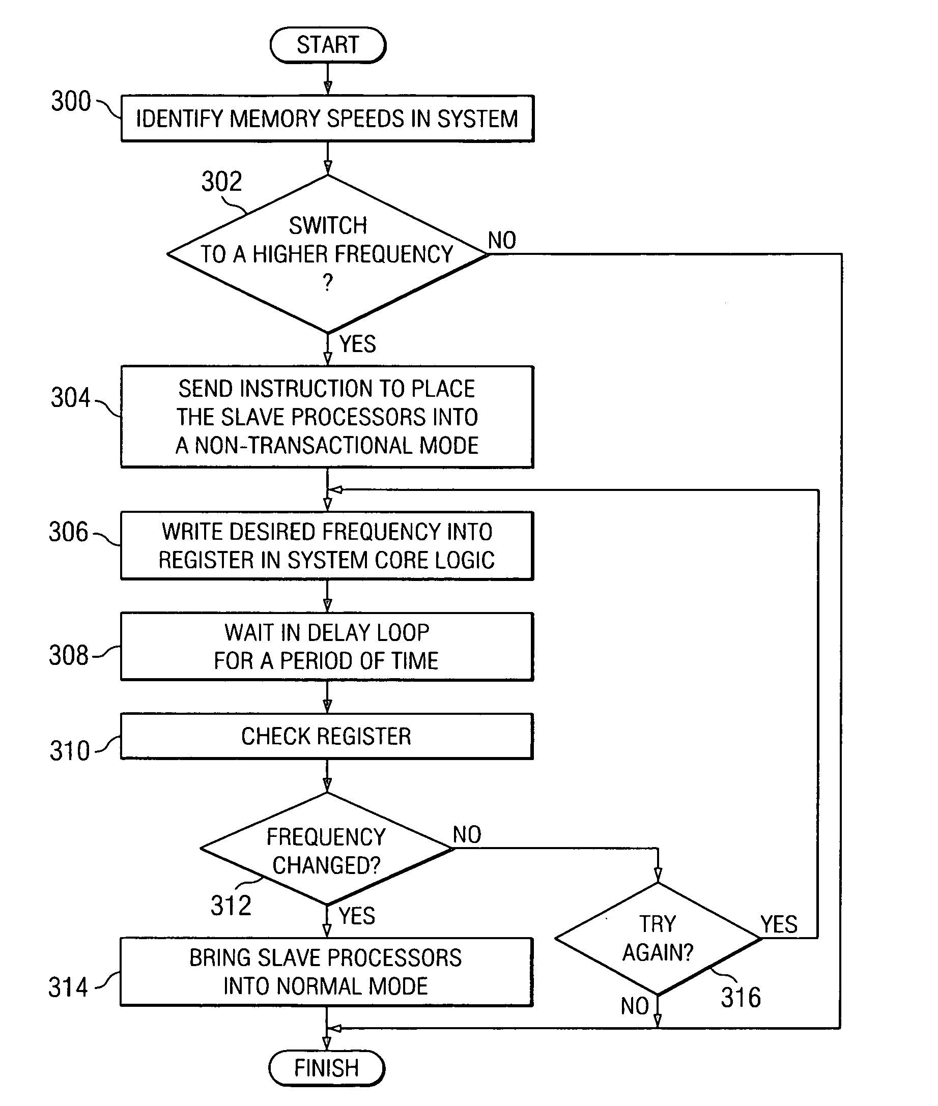
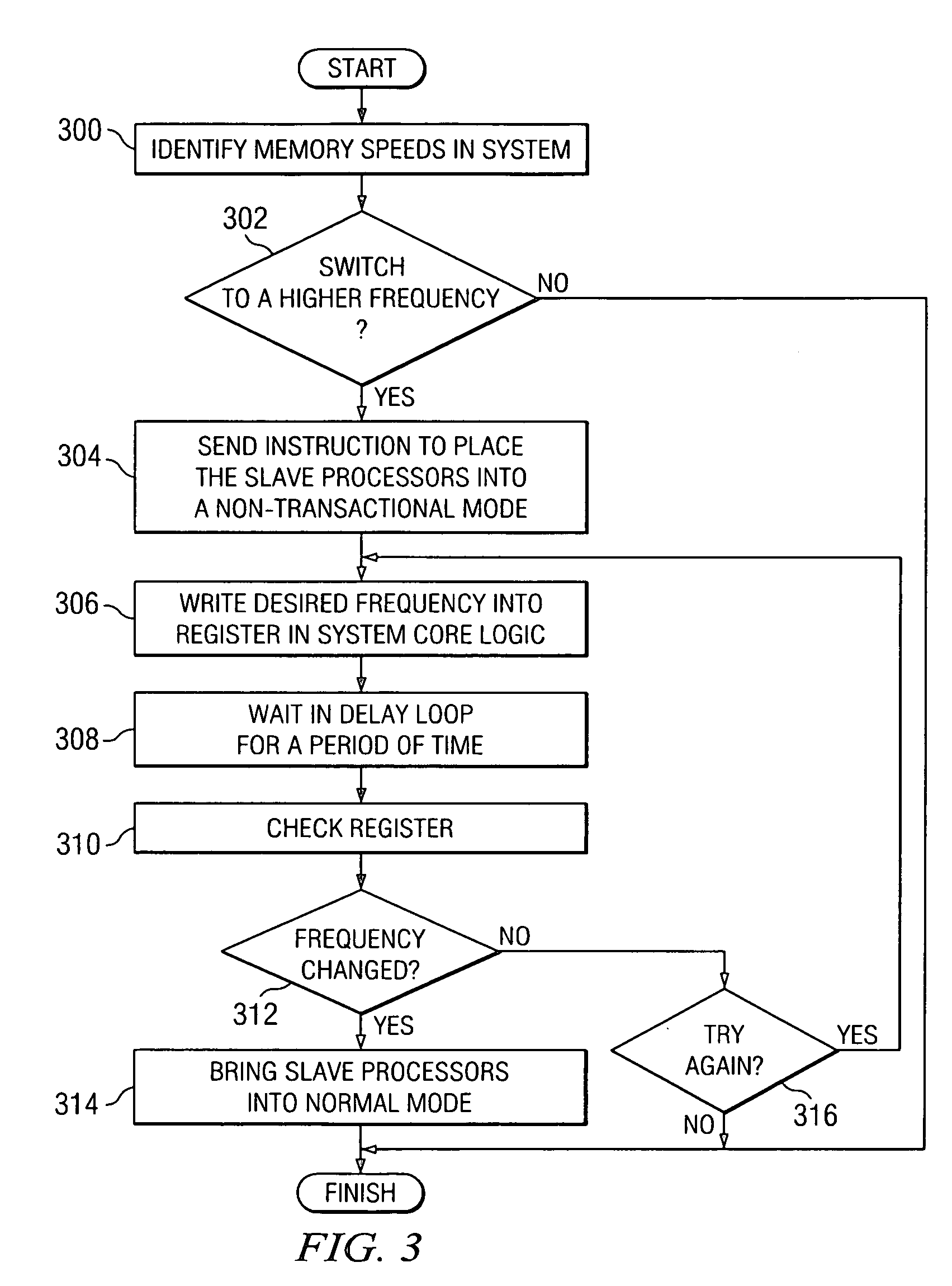
The present invention provides a way to change the frequency at which a system core logic interacts with memory in a multi-processor data processing system. This is done by determining if the default frequency should be changed and then placing the slave processors in a non-transactional mode. The master processor then changes the operating frequency in the system core logic to the new frequency. This allows for more efficient processing and faster data processing.

Problems solved by technology

Dynamic switching of the core frequency is hazardous and must be carefully handled to avoid a system crash.
The setting of this frequency is made more complicated if the data processing system cannot set the frequency from the BIOS.
Additionally, when a data processing system has multiple processors, the possibility of a system crash increases when dynamic switching of the core frequency is attempted.

Method used


Image

  • Method and apparatus to change the operating frequency of system core logic to maximize system memory bandwidth
  • Method and apparatus to change the operating frequency of system core logic to maximize system memory bandwidth
  • Method and apparatus to change the operating frequency of system core logic to maximize system memory bandwidth

Examples


Embodiment Construction

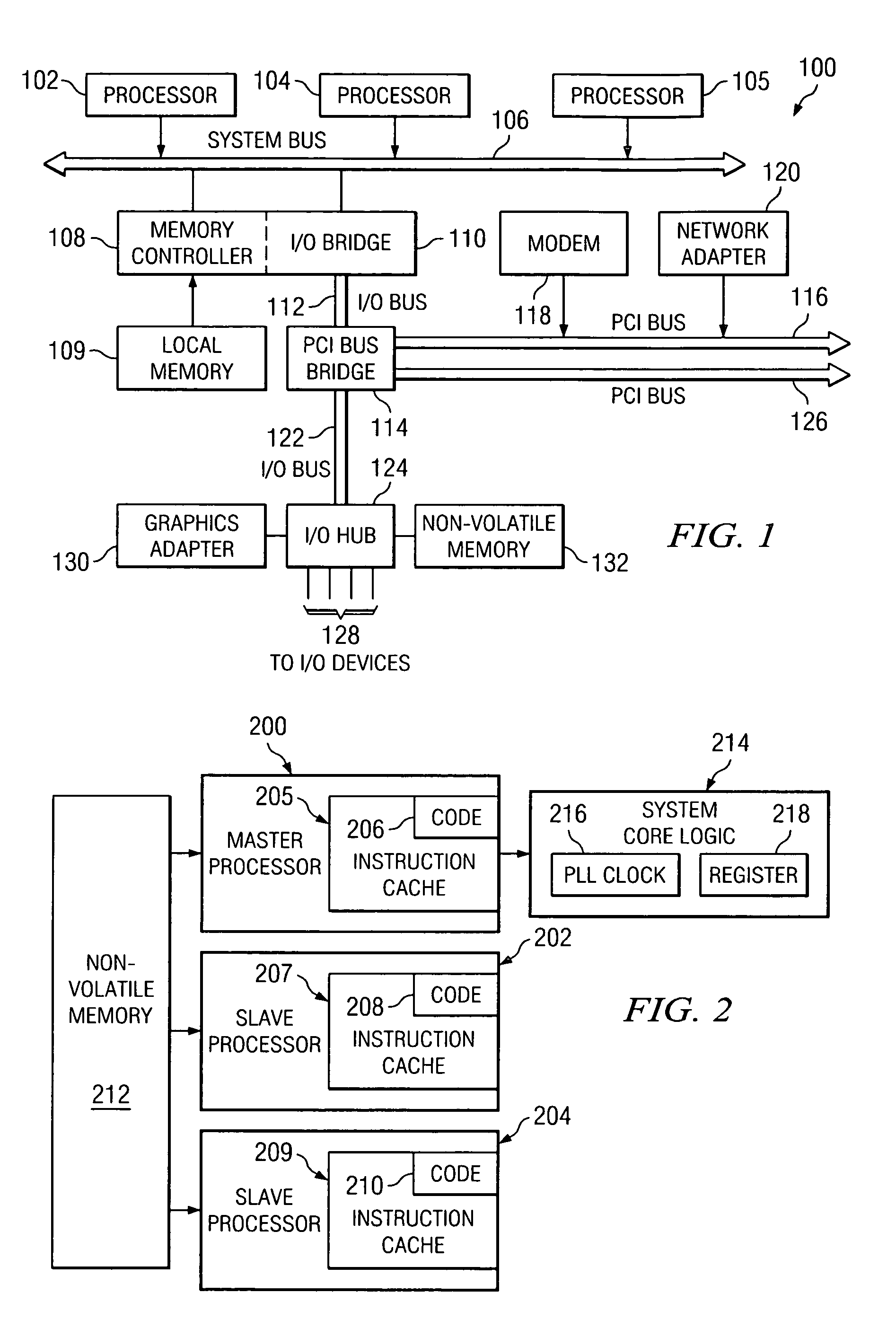
[0013] Referring to FIG. 1, a block diagram of a data processing system is depicted in accordance with a preferred embodiment of the present invention. Data processing system 100 is an example of a multi-processor computer system. In these illustrative examples, data processing system 100 is a symmetric multiprocessor (SMP) system including processors 102, 104, and 105 connected to system bus 106. Although only three processors are depicted, the present invention may be implemented using a data processing system with other numbers of processors. Alternatively, a single processor system may be employed. In a single processor system, the processor will always be the master processor. Therefore, the method is reduced to that the master processor loads the frequency switching routine into its instruction cache, writes the control register to change frequency, and waits in a predefined delay interval for the change to take place.

[0014] Also connected to system bus 106 is memory controll...


PUM


Abstract

A method, apparatus, and computer instructions for changing an operating frequency for a system core logic used to interface to memory in the multi-processor data processing system. A determination is made as to whether the operating frequency should be changed from a default frequency to another frequency. Slave processors are placed in the multi-processor data processing system into a non-transactional mode, in response to determining the operating frequency should be changed from the default operating frequency to the another operating frequency. When the slave processors are in the non-transactional mode, the operating frequency is changed in the system core logic to other operating frequency by the master processor.

Description

BACKGROUND OF THE INVENTION [0001] 1. Technical Field [0002] The present invention relates generally to an improved data processing system and in particular to a method and apparatus for processing data. Still more particularly, the present invention relates to a method, apparatus, and computer instructions for changing operating frequencies in a system core logic in a data processing system. [0003] 2. Description of Related Art [0004] A data processing system contains many different components that are interconnected to each other through a communications system, such as a bus. These components include a processor, a memory, and various input / output (I / O) adapters or components. The processor executes instructions in a fashion regulated by a clock rate. Additionally, other components, such as the bus and memory, also operate at a selected clock rate. An internal clock is provided to regulate and synchronize the operation of these and other components within the data processing syst...

Claims


Application Information

Patent Timeline
Patent Type & Authority Applications(United States)
IPC IPC(8): G06F1/08G06F12/00G06F1/26G06F1/32G06F9/30G06F13/00
CPCG06F1/3203Y02B60/1217G06F9/30101G06F1/324Y02D10/00G06F13/00
Inventor LEE, VAN HOA
Owner IBM CORP
Learn More