Method and a device for detecting flash gas

a detection device and flash gas technology, applied in the direction of instruments, heat measurement, lighting and heating apparatus, etc., can solve the problems of restricting flow and high cost of flow meters

Inactive Publication Date: 2005-08-04
DANFOSS AS
View PDF46 Cites 13 Cited by
  • Summary
  • Abstract
  • Description
  • Claims
  • Application Information

AI Technical Summary

Benefits of technology

[0009] An object of the invention is to provide a method for early detection of flash gas with a minimum number of false alarms.

Problems solved by technology

Such flow meters are expensive and may further restrict the flow.

Method used


Image

  • Method and a device for detecting flash gas
  • Method and a device for detecting flash gas
  • Method and a device for detecting flash gas

Examples


Embodiment Construction

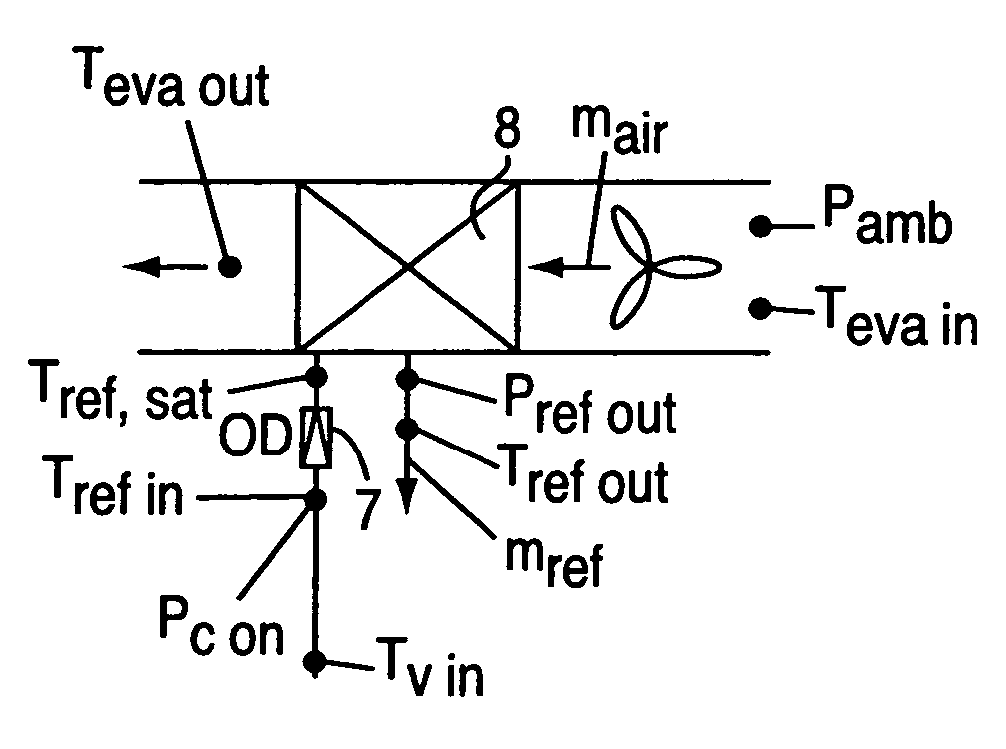
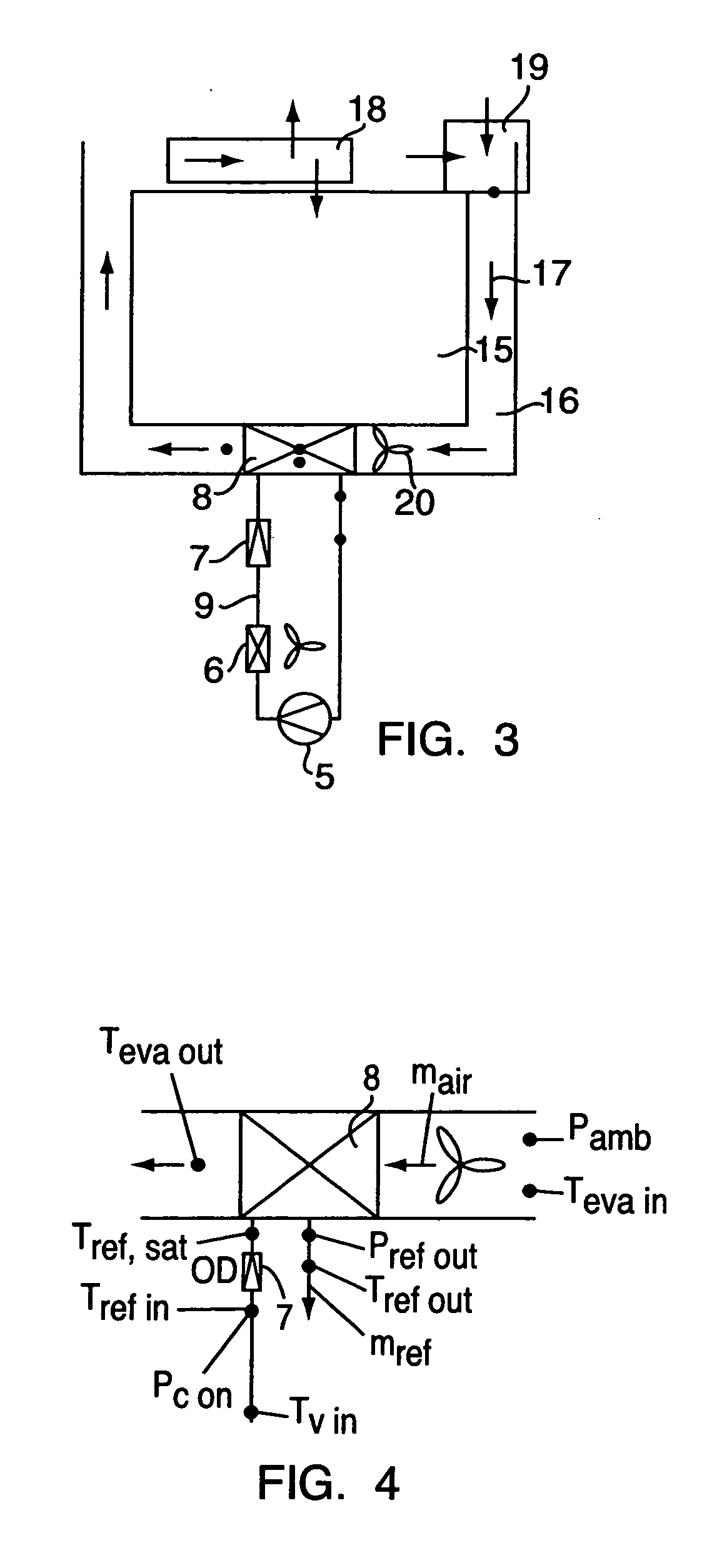
[0037] In the following reference will be made to a simple refrigeration system, although the principle is equally applicable to a heat pump system, and as understood by the skilled person, the invention is in no way restricted to a refrigeration system.

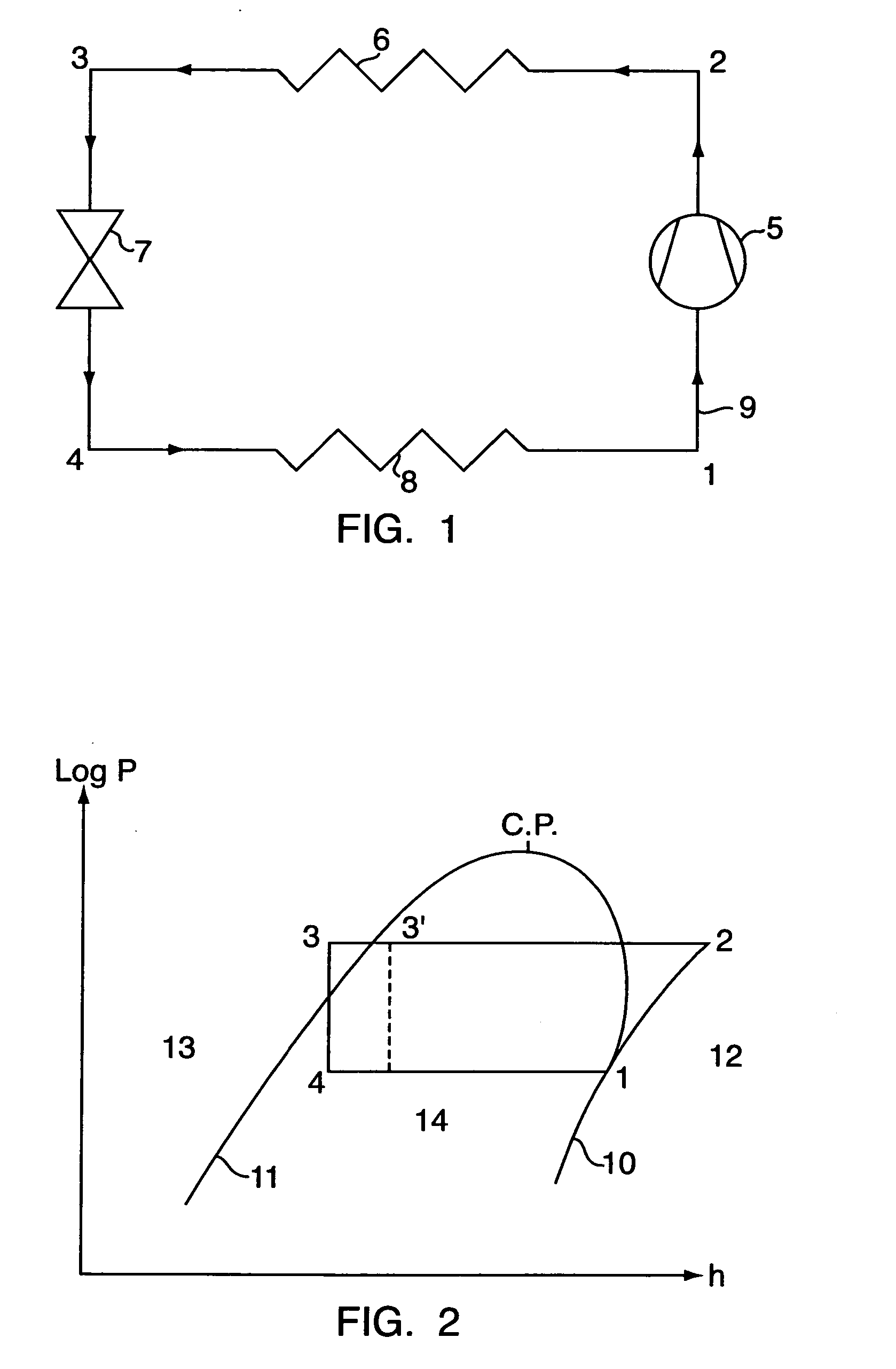
[0038] A simple refrigeration system is shown in FIG. 1. The system comprises a compressor 5, a condenser 6, an expansion device 7 and an evaporator 8 interconnected by conduits 9 in which a refrigerant is flowing. The mode of operation of the system is well known and comprises compression of a gaseous refrigerant from a temperature and pressure at point 1 before the compressor 5 to a higher temperature and pressure at point 2 after the compressor 5, condensing the refrigerant under heat exchange with a heat exchange fluid in the condenser 6 to achieve liquid refrigerant at high pressure at point 3 after the condenser 6. The high-pressure refrigerant liquid is expanded in the expansion device 7 to a mixture of liquid and gaseous ref...


PUM

PropertyMeasurementUnit
heat flowaaaaaaaaaa
specific enthalpyaaaaaaaaaa
mass flowaaaaaaaaaa

Abstract

A method and a device for detecting flash gas in a vapour-compression refrigeration or heat pump system comprising a compressor, a condenser, an expansion device, and an evaporator interconnected by conduits providing a flow path for a refrigerant, by determining a first rate of heat flow of a heat exchange fluid flow across a heat exchanger of the system and a second rate of heat flow of the refrigerant across the heat exchanger, and using the rates of heat flow for establishing an energy balance from which a parameter for monitoring the refrigerant flow is derived, to thereby provide early detection of flash gas with a minimum number of false alarms.

Description

CROSS REFERENCE TO RELATED APPLICATIONS [0001] This application is entitled to the benefit of and incorporates by reference essential subject matter disclosed in international Patent Application No. PCT / DK2003 / 000468 filed on Jul. 3, 2003 and Danish Patent Application No. PA 2002 01072 filed on Jul. 8, 2002.FIELD OF THE INVENTION [0002] The present invention relates to a method and a flash gas detection device for detecting flash gas in a vapour-compression refrigeration or heat pump system comprising a compressor, a condenser, an expansion device, and an evaporator interconnected by conduits providing a flow path for a refrigerant. BACKGROUND OF THE INVENTION [0003] In vapour-compression refrigeration or heat pump systems the refrigerant circulates in the system and undergoes phase change and pressure change. In the system a refrigerant gas is compressed in the compressor to achieve a high pressure refrigerant gas, the refrigerant gas is fed to the condenser (heat exchanger), where...

Claims


Application Information

Patent Timeline
Patent Type & Authority Applications(United States)
IPC IPC(8): F25B49/00F25B49/02
CPCF25B49/005F25B2500/222F25B2500/19
Inventor THYBO, CLAUSRASMUSSEN, BJARNE DINDLERLAURIDSEN, STEENHELBERG, VAGN
Owner DANFOSS AS
Why Eureka
Try Eureka