Horizontal multiple articulation type robot

a multi-joint, robot technology, applied in the direction of mechanical control devices, process and machine control, instruments, etc., can solve the problems of long path between two points, difficult to determine the layout of the position effective arrangement (in the shortest distance) of the robot, and reduce the cost. , the effect of wiring problems

Inactive Publication Date: 2005-08-04
SEIKO EPSON CORP
View PDF0 Cites 24 Cited by
  • Summary
  • Abstract
  • Description
  • Claims
  • Application Information

AI Technical Summary

Benefits of technology

[0023] By virtue of this construction, the wiring of a motor and the like can extend through the respective joint shafts and the arms without exposing the wiring. Therefore, troubles due to wiring (collision with peripheral obstacles and the like) can be eliminated and reduction in cost is possible.

Problems solved by technology

A horizontal multijoint type robot of the prior art, however, includes a second arm which could not rotate more than 360 degrees owing to its structural limitation so that its operating area is of substantially a doughnut shape thus attended by the following problems.
(1) There are areas within which the robot could not be operated unless only a single arm is operated so that moving paths between two points would become lengthy, taking much time.
(2) As the region (working range) in which the robot is operated is narrower, there are many limitations in a limited space so that it would be very difficult to determine a layout for effectively arranging positions (in shortest distances) where the robot operates.
(3) If a wider operating range is attempted, the size of a robot would have to be enlarged in proportion to the working area, causing a problem of space.

Method used


Image

  • Horizontal multiple articulation type robot
  • Horizontal multiple articulation type robot
  • Horizontal multiple articulation type robot

Examples


embodiment 1

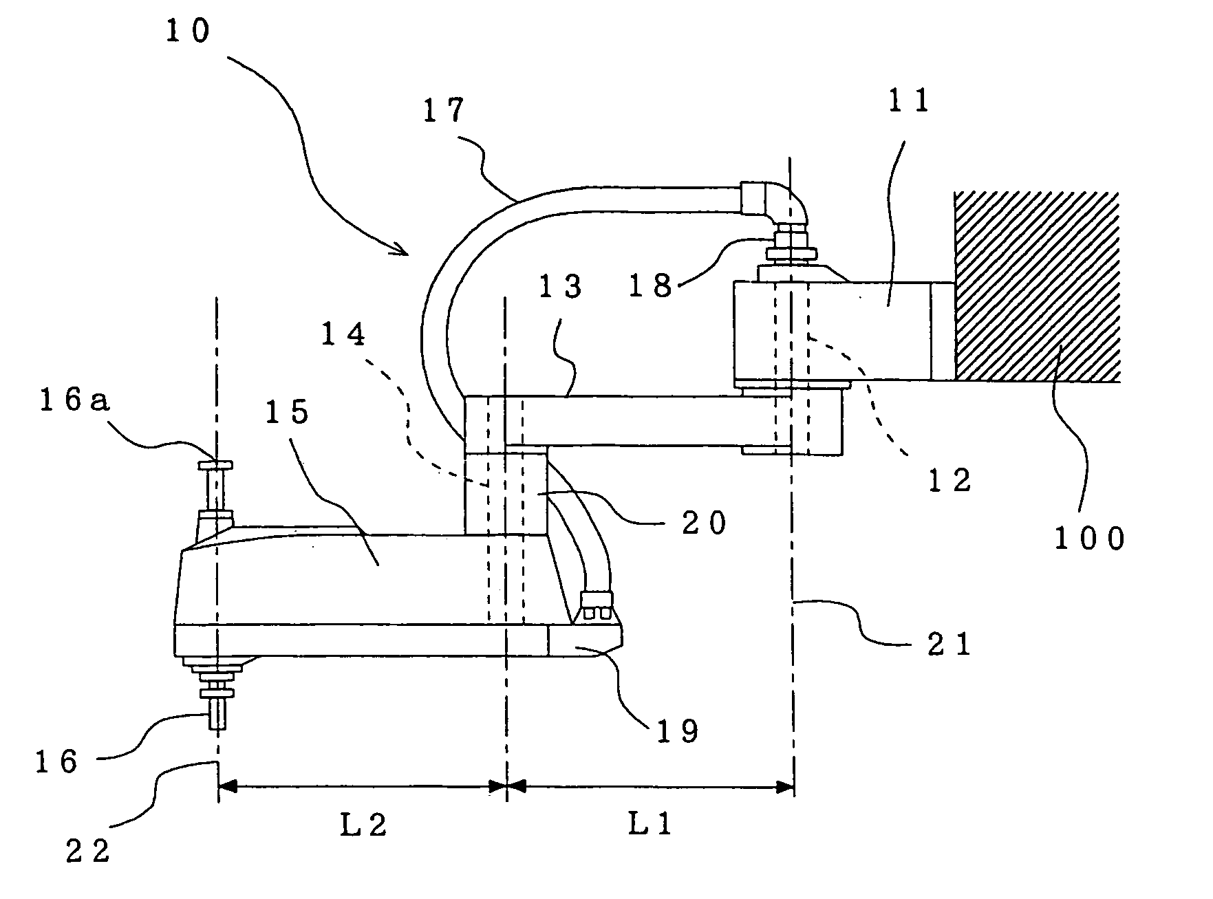
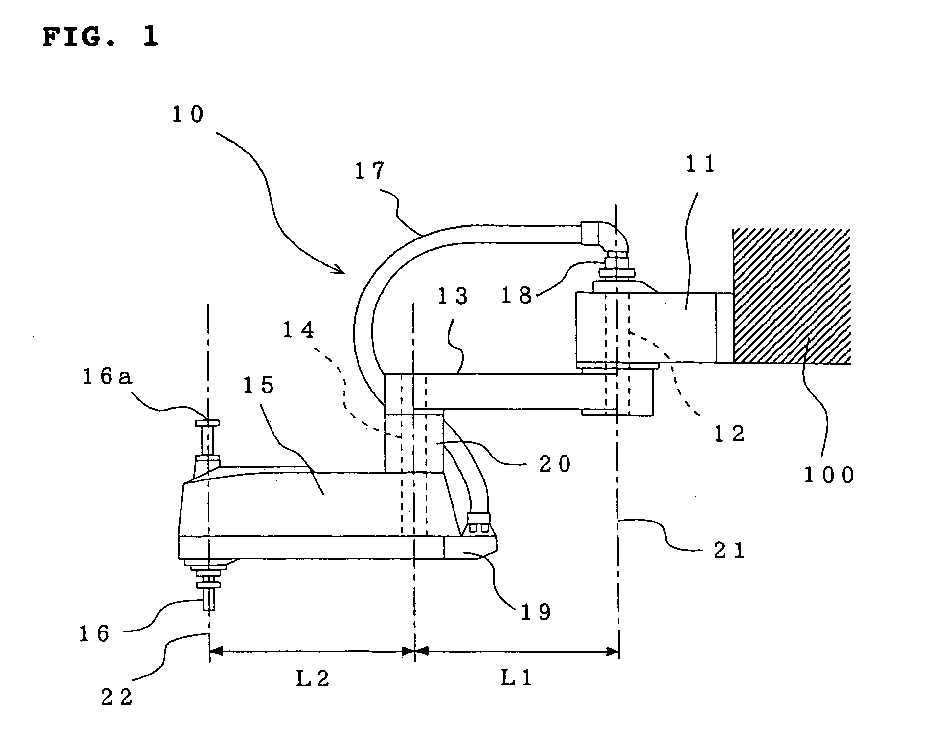
[0032]FIG. 1 is a side view of the horizontal multijoint type robot according to the embodiment 1, and FIG. 2 is a side view illustrating one operating mode of the horizontal multijoint type robot.

[0033] The horizontal multijoint type robot 10 comprises a base 11, a first arm 13 connected through a first joint shaft 12 to the base 11, a second arm 15 connected through a second joint shaft 14 to the first arm 13 and a working shaft 16 provided rotatably and movably up and down on the distal end of the second arm 15. Mounted onto the working shaft 16 is a handling device or other tool (not shown) for assembling, transferring, inspection or the like in accordance with a working purpose. Moreover, the arm length L1 of the first arm 13 (a distance between the center of the first joint shaft 12 and the center of the second joint shaft 14) and the arm length L2 of the second arm 15 (a distance between the center of the second joint shaft 14 and the center of the working shaft 16) are equa...

embodiment 2

[0045] Although the embodiment described above uses the two arms and the lengths L1 of the first arm 13 and the length L2 of the second arm 15 are equal to each other, the present embodiment 2 using three arms will be explained with reference to FIGS. 5 and 6. In the case of the horizontal multijoint type robot, maximum of three arms may be sufficient in practical use.

[0046]FIG. 5 is a schematic side view of a horizontal multijoint type robot according to this embodiment, and FIG. 6 is a view illustrating an operating area of the robot of this embodiment.

[0047] As can be seen from the explanation of the operating area of the robot in FIG. 3 described above in the case that the length L1 of the first arm 13 and the length L2 of the second arm 15 are different from each other, the operation impossible area having a radius which is difference between L1 and L2 will occur about the center of the first joint shaft 12. In other words, when the length of the second arm 15 is shorter or l...

embodiment 3

[0052]FIG. 7 is a partly sectional side view of a horizontal multijoint type robot according to the embodiment 3.

[0053] In this mode, there is disclosed one example of a driving mechanism for each joint shaft 12 and 14 in the case using two arms. The case using three arms is similar to the case of two arms.

[0054] In this embodiment, both the first joint shaft 12 and the second joint shaft 14 are made from hollow shafts through which wirings 36 extend. Also, the first arm 13 and the second arm 15 have a hollow portion 37 and 38 for extending wirings therethrough.

[0055] The first joint shaft 12 and the second joint shaft 14 made of the hollow shafts are rotationally driven by a first motor 43 and a second motor 44 through a first reduction machine 41 and a second reduction machine 42 respectively formed of a harmonic drive mechanism. Also, reference numeral 45 denotes a first timing belt mechanism provided between the first motor 43 and the reduction machine 41, and numeral 46 a se...


PUM


Abstract

A horizontal multijoint type robot is so constructed that it comprises a first arm connected through a first joint shaft to a base, a second arm connected through a second joint shaft to the first arm, and a working shaft provided rotatably and movably up and down on the distal end of the second arm, and that the arm length L1 of the first arm and the arm length L2 of the second arm are equal to each other so that the second arm is able to overlap the first arm.

Description

CROSS REFERENCE TO RELATED APPLICATIONS [0001] This application claims priority to Japanese patent application No. 2004-003793 filed on Jan. 9, 2004 which is hereby incorporated by reference. BACKGROUND OF THE INVENTION [0002] 1. Field of the Invention [0003] The present invention relates to a horizontal multijoint type robot having a greatly enlarged region within which the robot is able to operate. [0004] 2. Related Art [0005] The horizontal multijoint type robot also called as scalar type robot usually includes a first arm and a second arm pivotally movable in horizontal planes through a first and a second joint shaft, respectively, a working shaft equipped on the distal end of the second arm and rotatable and movable up and down, and a handling device or the like mounted on the working shaft for carrying out desired working such as assembling, transferring or the like (refer to, for example, Japanese Patent Application Laid Open No. 84,688 / 1993). [0006] A horizontal multijoint t...

Claims


Application Information

Patent Timeline
Patent Type & Authority Applications(United States)
IPC IPC(8): B25J9/06B25J9/04B25J19/00
CPCB25J9/044B25J18/04Y10S901/27B25J9/06Y10T74/20305Y10T74/20311Y10T74/20329Y10S901/28B25J9/042
Inventor MEYERHOFF, CHRISTOPHAKAHA, KAZUSHIGE
Owner SEIKO EPSON CORP
Why Eureka
Try Eureka