Liquid chromatograph

a liquid chromatograph and chromatograph technology, applied in the field of liquid chromatographs, can solve the problems of reduced separation performance of analysis columns, difficult to change plumbing, and difficulty in highly sensitive analysis

Active Publication Date: 2005-08-04
SHIMADZU CORP
View PDF8 Cites 17 Cited by
  • Summary
  • Abstract
  • Description
  • Claims
  • Application Information

AI Technical Summary

Benefits of technology

[0009] An object of the present invention is to provide a liquid chromatograph capable of switching between online concentration analysis and direct analysis not involving concentration, without a change in plumbing.

Problems solved by technology

When the sample injected into the injection port is of large quantity, a band of the sample in the analysis column is broadened by action of a solvent contained in the sample, so that the separation performance of the analysis column is reduced, thereby posing difficulty in highly-sensitive analysis.
Operation for changing the plumbing is very complicated, and involves consumption of much time and consideration for prevention of leakage which would otherwise arise after changing of the plumbing; particularly, a dead volume in the plumbing for which micro flow rate or nano flow rate is critical.

Method used


Image

  • Liquid chromatograph
  • Liquid chromatograph
  • Liquid chromatograph

Examples


first embodiment

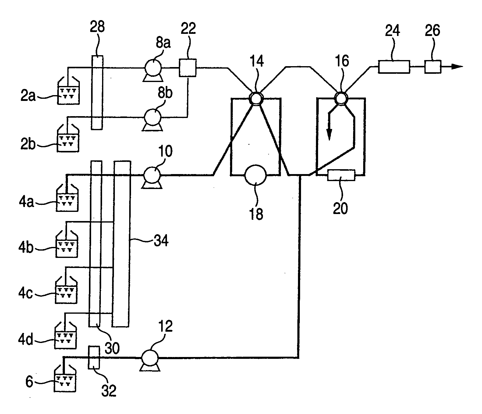
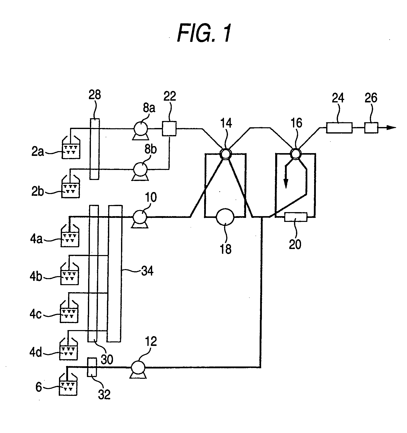
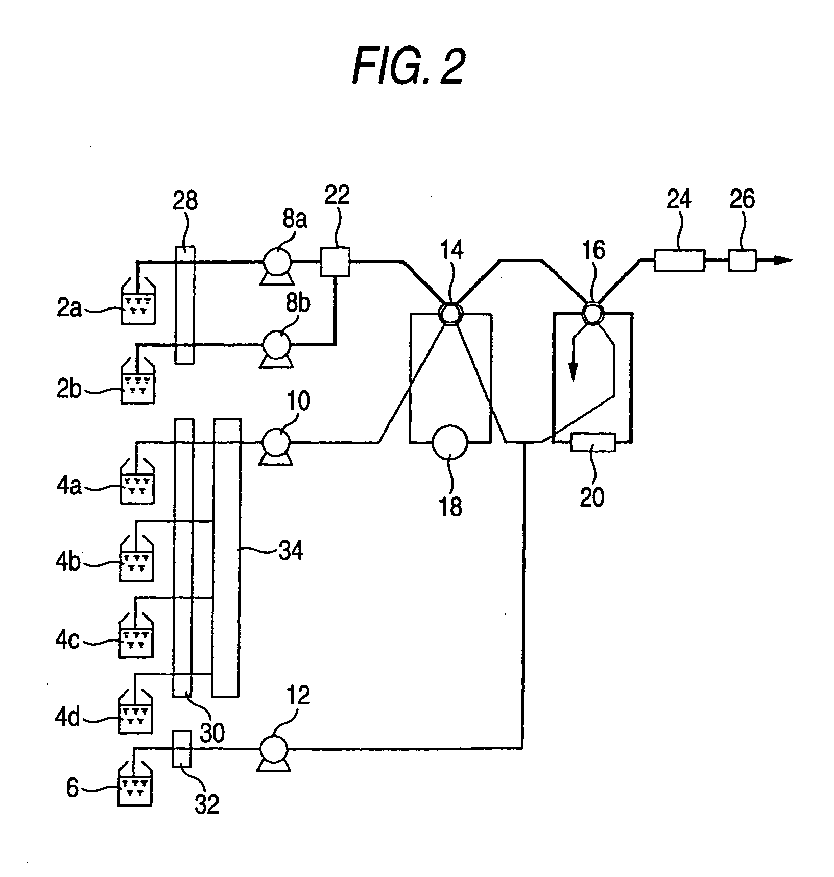
[0024] An embodiment will be provided below. FIGS. 1, 2, and 3 are flow passage diagrams showing an embodiment of a liquid chromatograph according to the present invention. FIG. 1 shows a flow passage achieved at the phase of concentration of a sample, FIG. 2 shows a flow passage achieved at the phase of concentration analysis, and FIG. 3 shows a flow passage achieved at the phase of direct analysis.

[0025] The liquid chromatograph has switching valves 14, 16 as a flow passage switching mechanism, and an automatic sampler 18 as an injection section. The liquid chromatograph can switch, by switching the switching valves 14, 16, between a concentration flow passage for concentrating the sample injected by the automatic sampler 18; a concentration analysis flow passage for separating the trapped sample on a per-composition basis; and a direct analysis flow passage for separating the sample on a per-composition basis. The concentration flow passage connects the automatic sampler 18 to a...

second embodiment

[0037] There will be described hereinbelow a second embodiment where a second trapping column is provided in the flow passage of the liquid chromatograph described in connection with the first embodiment. FIG. 4 is a flow passage diagram showing the configuration of a liquid chromatograph having two trapping columns.

[0038] A switching valve 17 and a second trapping column 21 are provided downstream of the switching valve 16 and the trapping column 20 shown in FIGS. 1 through 3. This apparatus is configured to simultaneously enable concentration of a sample and analysis of the concentrated sample.

[0039] Operation of the liquid chromatograph of the present embodiment will be described hereinbelow.

[0040] Concentration of the sample is performed as follows. Namely, the mobile phase switching valve 34 selects any one from the mobile phases 4a, 4b, 4c, and 4d and sends the thus-selected mobile phase to the automatic sampler 18 by the pump 10. The automatic sampler 18 aspirates a sample...


PUM

PropertyMeasurementUnit
liquidaaaaaaaaaa
concentrationaaaaaaaaaa
flow rateaaaaaaaaaa

Abstract

A liquid chromatograph has switching valves as a flow passage switching mechanism and an automatic sampler as an injection section. The liquid chromatograph can switch, by switching the switching valves between a concentration flow passage for concentrating the sample injected by the automatic sample via a flow passage which connects the automatic sampler to the trapping column; a concentration analysis flow passage for separating and analyzing the concentrated sample on a per-composition basis which connects the trapping column to the analysis column; and a direct analysis flow passage by separating the sample on a per-composition basis which connects the automatic sampler to the analysis column.

Description

BACKGROUND OF THE INVENTION [0001] 1. Field of the Invention [0002] The present invention relates to a liquid chromatograph having a trapping column for analyzing a dilute sample through concentration. [0003] 2. Description of the Related Art [0004] In relation to a high-performance liquid chromatograph, when a sample is injected into an injection port, the thus-injected sample is usually sent to an analysis column by means of a mobile phase sent by a liquid delivery pump, and the sample is separated by the analysis column. When the sample injected into the injection port is of large quantity, a band of the sample in the analysis column is broadened by action of a solvent contained in the sample, so that the separation performance of the analysis column is reduced, thereby posing difficulty in highly-sensitive analysis. However, in the analysis of a diluted sample, a large quantity of sample must be injected in order to increase the absolute quantity of sample during analysis. In su...

Claims


Application Information

Patent Timeline
Patent Type & Authority Applications(United States)
IPC IPC(8): G01N30/26B01D15/08G01N30/06G01N30/08G01N30/46G01N30/80
CPCG01N30/08G01N2030/085G01N30/468
Inventor IWATA, YOSUKE
Owner SHIMADZU CORP
Why Eureka
Try Eureka