Automatic sampler for liquid chromatograph

a liquid chromatograph and sampler technology, applied in the field of automatic samplers, can solve the problems of troublesome replacement of plungers, prolong sample intake time, etc., and achieve the effects of high accuracy, short time, and large amount of solution

Active Publication Date: 2011-09-01
SHIMADZU CORP
View PDF1 Cites 22 Cited by
  • Summary
  • Abstract
  • Description
  • Claims
  • Application Information

AI Technical Summary

Benefits of technology

[0012]It is an object of the present invention to provide an automatic sampler for a liquid chromatograph cap

Problems solved by technology

If the intake amount of the sample is large or at the time of intake of the rinse solution, the intake amount cannot be treated by a stroke of driving of the plunger, and it is necessary to repeat intake and discharge operations a plurality of times, which prolongs intake t

Method used


Image

  • Automatic sampler for liquid chromatograph
  • Automatic sampler for liquid chromatograph
  • Automatic sampler for liquid chromatograph

Examples


Embodiment Construction

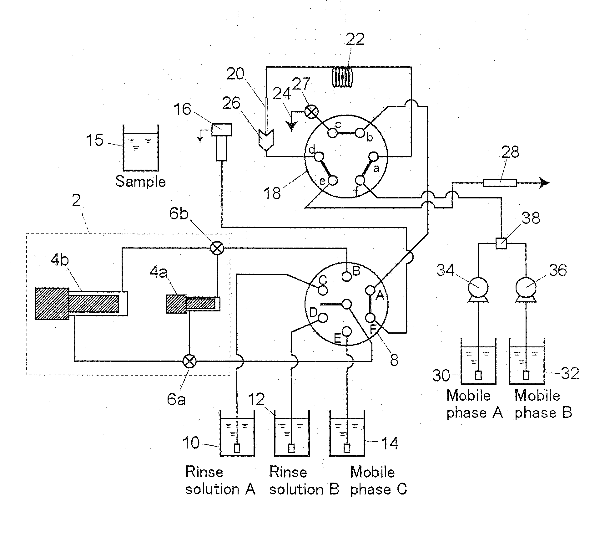
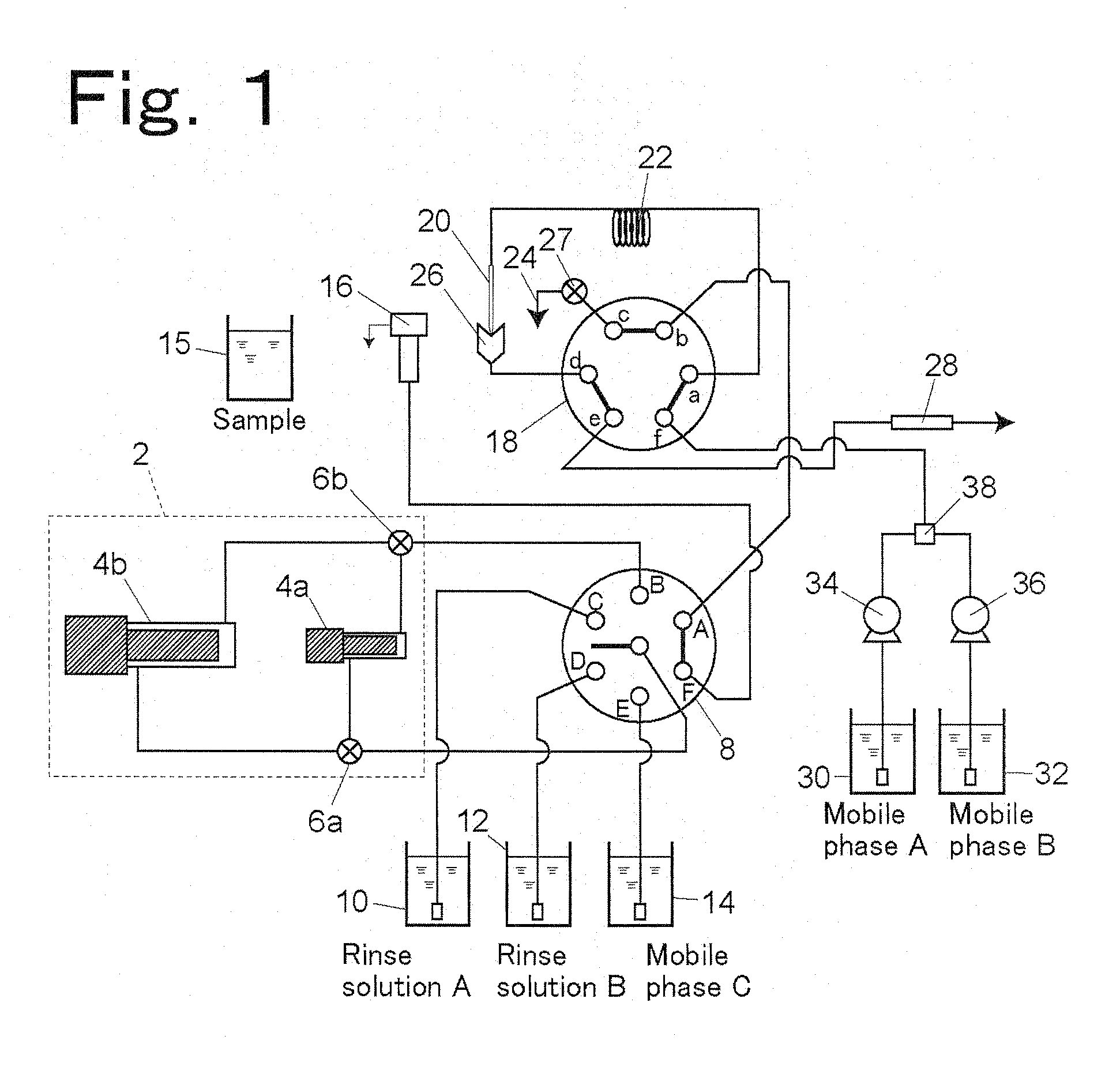
[0029]An embodiment of an automatic sampler will be described by using FIG. 1.

[0030]A pump portion 2 for taking in and discharging solutions has two plunger pumps including a first plunger pump 4a and a second plunger pump 4b. Both the plunger pumps 4a and 4b have different cylinder capacities and different solution intake and discharge amounts per stroke of the plungers. The second plunger pump 4b has a larger cylinder capacity than the first plunger pump 4a. For example, the cylinder capacity of the first plunger pump 4a is 100 μL, and the cylinder capacity of the second plunger pump 4b is 400 μL.

[0031]Both the plunger pumps 4a and 4b are connected to a first switching valve 8. Besides a common port connected to intake ports of the plunger pumps 4a and 4b, the first switching valve 8 includes a port “A” connected to a port “b” of a second switching valve 18, a port “B” connected to discharge ports of the plunger pumps 4a and 4b, ports “C” to “E” respectively connected to a vessel ...


PUM


Abstract

A pump portion for taking in and discharging solutions includes a first plunger pump with a small capacity and a second plunger pump with a large capacity. Intake ports of both the plunger pumps are connected in parallel to a common port of a switching valve with a first three-way valve interposed therebetween. The first three-way valve connects the intake port of one of the plunger pumps to the switching valve. Discharge ports of both the plunger pumps are connected in parallel to one port of the switching valve with a second three-way valve interposed therebetween. The second three-way valve connects the discharge port of one of the plunger pumps to the switching valve.

Description

BACKGROUND OF THE INVENTION[0001]1. Field of the Invention[0002]The present invention relates to an automatic sampler for automatically injecting a sample into an analytical flow path of a liquid chromatograph.[0003]2. Description of Background Technique[0004]A common automatic sampler for automatically injecting a sample into an analytical flow path of a liquid chromatograph is formed to take in a predetermined amount of a sample with a metering pump with a needle inserted in a sample vessel and to inject the taken-in sample into the liquid chromatograph (see Japanese Patent Application Laid-Open No. 2005-99056, for example).[0005]FIG. 10 shows an example of a prior-art automatic sampler with a liquid chromatograph.[0006]In this automatic sampler, by switching a first switching valve 8 and a second switching valve 18 and driving a needle 20, flow paths for carrying out a sample intake step, a step of introducing the sample into the liquid chromatograph, a step of cleaning the needl...

Claims


Application Information

Patent Timeline
IPC IPC(8): G01N30/24
CPCG01N30/24
Inventor MAEDA, YOSHIAKI
Owner SHIMADZU CORP
Why Eureka
Try Eureka