Method for transferring a pattern

a pattern and pattern technology, applied in the direction of printing press parts, instruments, semiconductor/solid-state device details, etc., can solve the problem of not teaching the pattern to be centered in relation to a rotational axis, and achieve the effect of less complicated and easy manufacturing

Inactive Publication Date: 2005-08-04
OBDUCAT AB SE
View PDF5 Cites 14 Cited by
  • Summary
  • Abstract
  • Description
  • Claims
  • Application Information

AI Technical Summary

Benefits of technology

[0022] It is possible to provide the alignment with the aid of a means which acts on the peripheries of the pressing means and the substrate. However, it is only by means of a method, in which the pressing means and the substrate are centered with the aid of through-holes in the pressing means and the substrate, that the full extent of the invention is exploited and a less complicated method is obtained.
[0023] If the substrate and the pressing means are centered by means of through-holes, a center through-hole is provided in the substrate, which center hole has a center axis that extends through the center of gravity of the substrate and coincides with a normal direction of said planar surfaces. The first pressing means has a first through-hole, which has a center axis that coincides with a normal direction of said first surface of said first pressing means. If a second pressing means is provided, this is provided with a second through-hole, which has a center axis that coincides with a normal direction of said second surface of said second pressing means. The step of arranging the center of said substrate and the centers of said first and, possibly, second structures on a common center line comprises arranging said substrate and said first and, possibly, second pressing means on a mandrel, which is arranged to extend through said center hole, first hole and, possibly, second hole. A mandrel which is arranged to extend through said center hole in the manner described above is much easier to manufacture than a means which is arranged to engage the peripheries of the substrate and the pressing means.

Problems solved by technology

However, SE01 / 00527 does not teach how the pattern can be centered in relation to a rotational axis.

Method used


Image

  • Method for transferring a pattern
  • Method for transferring a pattern
  • Method for transferring a pattern

Examples


Embodiment Construction

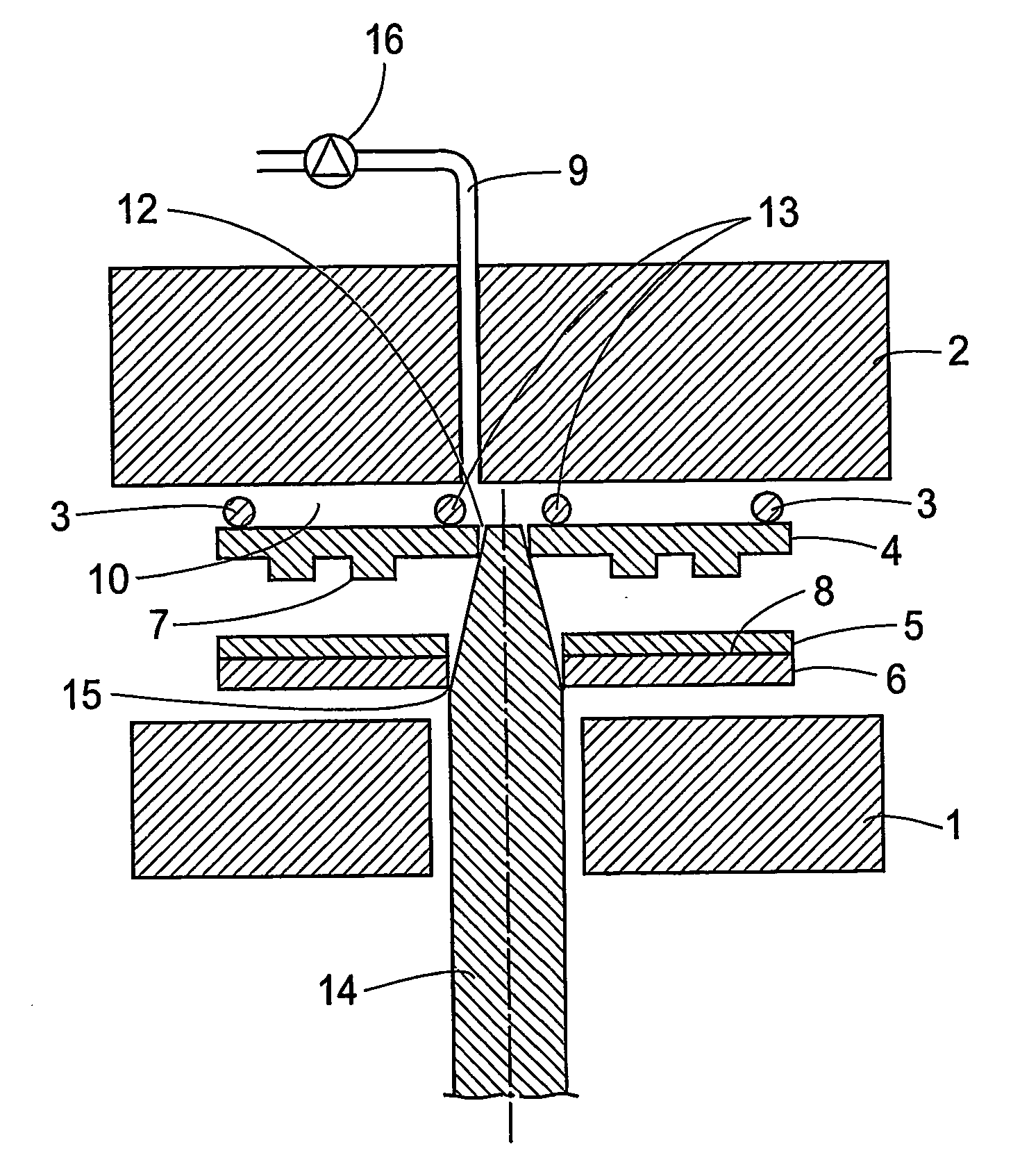
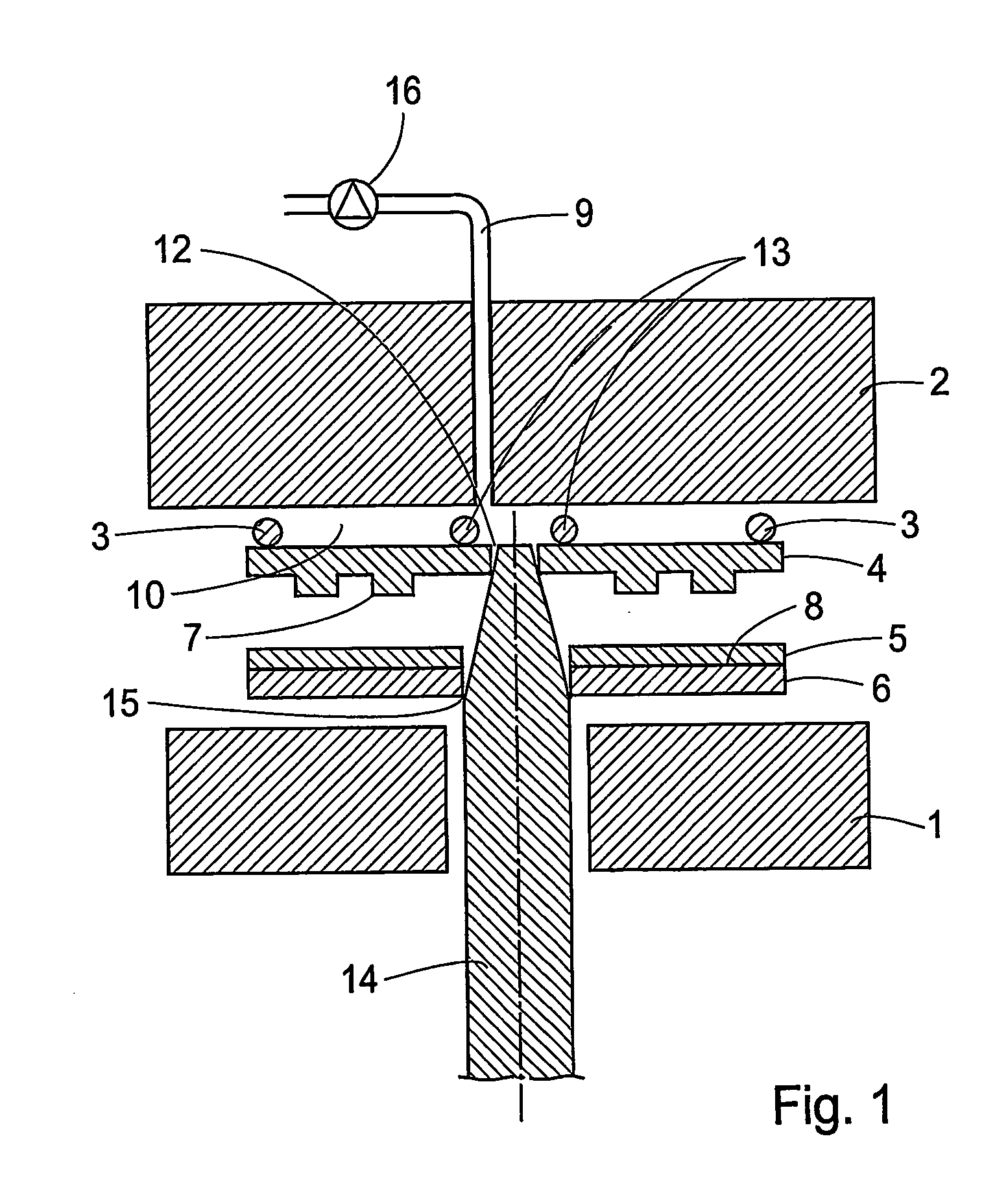
[0041]FIG. 1 illustrates a method according to a preferred embodiment of the invention. FIG. 1 shows a first holding means 1 and a second holding means 2 between which a pressure can be applied to press together a pressing means 4, which is provided with a structure 7, and a substrate 6, which on a first planar surface 8 is provided with a layer 5. Between the pressure means and the first holding means, a first sealing ring 3 and a second sealing ring 13 are arranged to form a chamber 10 which can be used to create a pressure by means of which the pressing means is pressed into the layer. The chamber 10 is formed when the first holding means has contacted the sealing rings. The pressure is generated by injecting high-pressure gas through the conduit 9. At the center of the second holding means 2, a centering means 14 protrudes which has a conical portion of circular cross-section at its top. In the pressing means, a first circular through-hole 12 is arranged which has the same diame...


PUM

PropertyMeasurementUnit
pressureaaaaaaaaaa
magneticaaaaaaaaaa
sizeaaaaaaaaaa

Abstract

A method and a device for forming at least a first pattern on a substrate (6,28), which is coated with a layer (5) on at least a first planar surface, are described. According to the method, a first pressing means (27) is arranged with a first structure (32) that defines the pattern, and the substrate (28) is arranged so that the first pressing means (27) is separated from the substrate (28) and so that the first pressing means (27) and the substrate (28) are unable to move transversely of the common center line (50) but are able to move freely in a direction first pressing means (27) is contacted with the substrate (28) while maintaining the common center line, and a pressure is applied to the substrate (28) and the first pressing means (27) to form said at least one pattern in the layer (30)

Description

FIELD OF THE INVENTION [0001] The present invention relates to a method and a device for transferring a pattern from a pressing means to an object. BACKGROUND ART [0002] Among other things in the semiconductor industry and in the manufacture of optical storage media, a pattern is to be transferred to an object. There are a number of different techniques for transferring a pattern to an object, such as optical lithography and electron beam lithography. A technique which has recently come into use and which, for instance, is used for manufacturing CDs (compact disks) is transferring a pattern by pressing. [0003] PCT Application SE01 / 00527 discloses a device and a method for transferring a pattern from a pressing means to a substrate, which is provided with a layer, by means of pressing. In the application, a technique to obtain an even pressure over the entire surface of the pressing means is described. [0004] In the manufacture of, among other things, rotating storage media, it is im...

Claims


Application Information

Patent Timeline
Patent Type & Authority Applications(United States)
IPC IPC(8): B29C39/02B29C59/02B29L31/34G03F7/00G11B5/82G11B5/84G11B5/855
CPCB29C59/02B29L2017/003B82Y10/00G11B5/855G03F7/0002G03F9/7053B82Y40/00
Inventor OLSSON, LENNART
Owner OBDUCAT AB SE
Why Eureka
Try Eureka