Method of determining pole arc ratio of interior permanent magnet rotary motor and interior permanent magnet rotary motor

a technology of permanent magnets and rotary motors, which is applied in the direction of magnetic circuit rotating parts, dynamo-electric machines, and shape/form/construction of magnetic circuits, etc., can solve the problems of motor vibration and speed variation, reduce torque, reduce the productivity of the motor, and reduce the amount of permanent magnets used. , the effect of reducing the torqu

Inactive Publication Date: 2005-08-04
SANYO DENKI CO LTD
View PDF7 Cites 35 Cited by
  • Summary
  • Abstract
  • Description
  • Claims
  • Application Information

AI Technical Summary

Benefits of technology

[0022] If the pole arc ratio Ψp of the motor is determined as in the present invention, the interior permanent magnet rotary motor, wh...

Problems solved by technology

Such cogging torque hinders smooth rotation or reciprocation of the motor, thus causing vibration and speed variation of the motor.
However, formation of the skew may reduce the torque or reduce the productivity of the motor.
Further, use of the per...

Method used


Image

  • Method of determining pole arc ratio of interior permanent magnet rotary motor and interior permanent magnet rotary motor
  • Method of determining pole arc ratio of interior permanent magnet rotary motor and interior permanent magnet rotary motor
  • Method of determining pole arc ratio of interior permanent magnet rotary motor and interior permanent magnet rotary motor

Examples


first embodiment

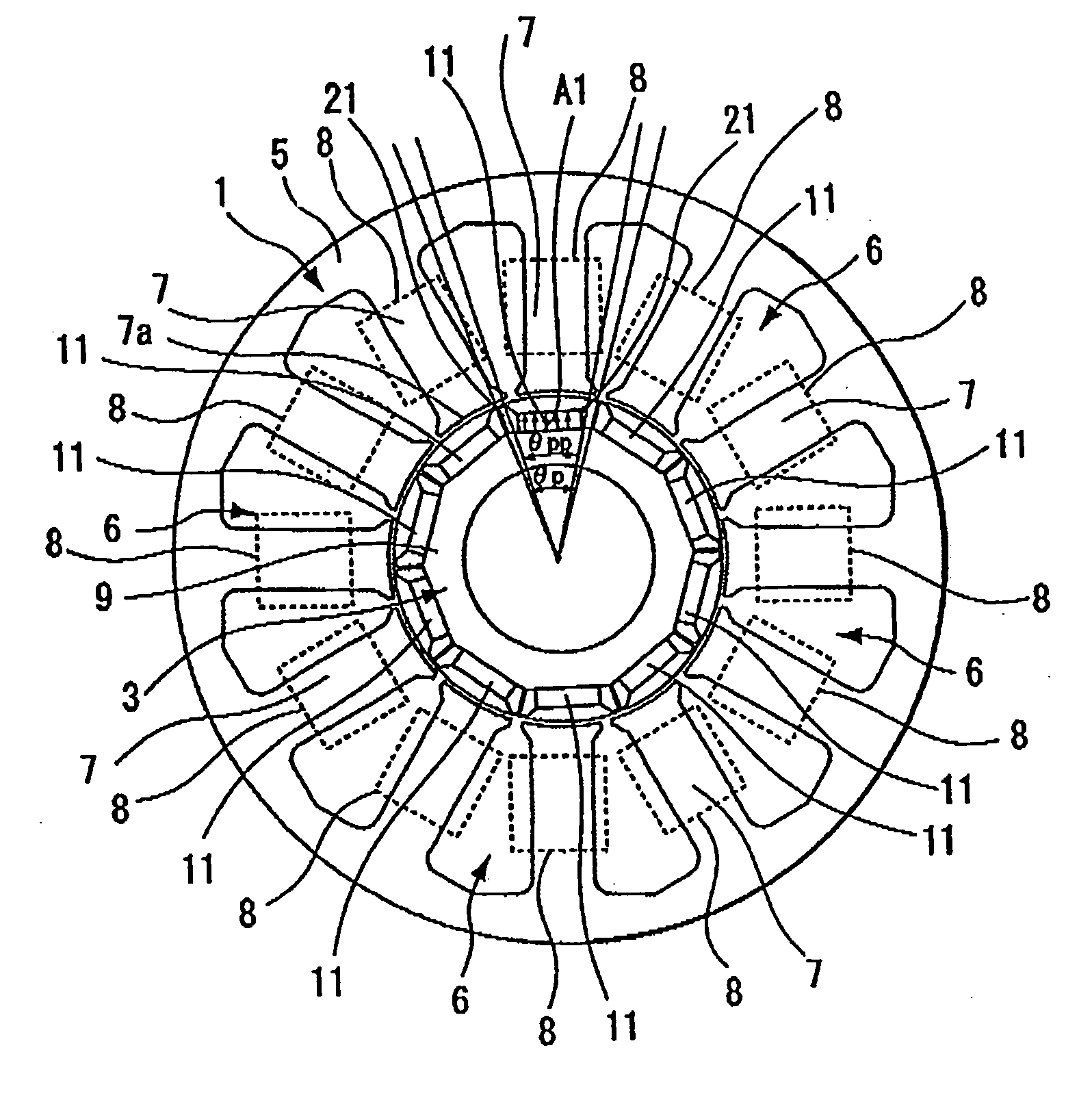
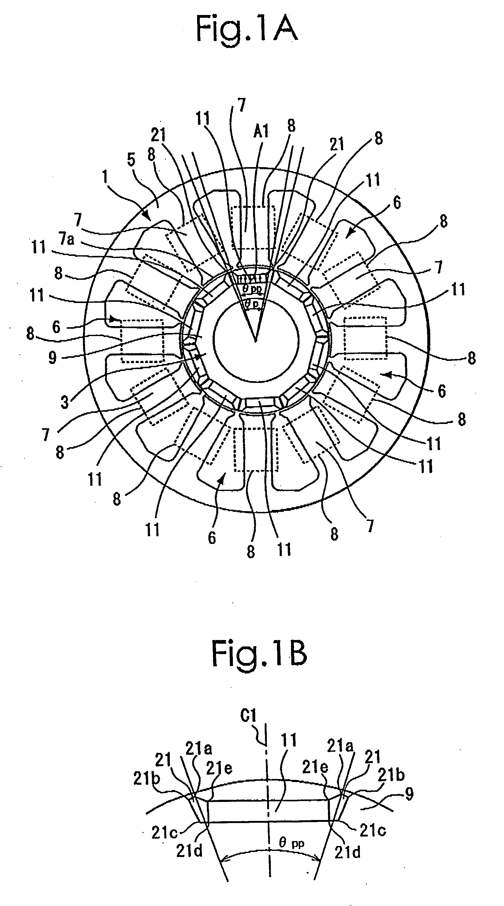
[0034] The best mode for carrying out the present invention will be described with reference to the appended drawings. FIG. 1(A) is a schematic diagram showing a stator 1 and a rotor 3 of an interior permanent magnetic rotary motor used for explaining the present invention. FIG. 1(B) is a partial enlarged view of FIG. 1(A). As shown in both of the drawings, the stator 1 includes a cylindrical yoke 5 and 12 magnetic pole sections 7 that protrude toward the center of the stator from the inner periphery of the yoke 5. Each of the 12 magnetic pole sections 7 has a magnetic pole surface 7a at a leading end thereof. With this arrangement, the stator 1 has N slots 6 (being 12, herein) arranged between respective adjacent pairs of the magnetic pole sections 7 which are spaced at equal intervals in a peripheral direction thereof. On each of the magnetic pole sections 7, a winding section 8 constituted from an exciting winding of two phases wound in a concentrated manner is formed. For facili...


PUM


Abstract

There is provided an interior permanent magnet rotary motor that can reduce cogging torque and can also reduce the amount of permanent magnet used, without reducing torque.
In an interior permanent magnet rotary motor of the present invention having N slots 6 and P permanent magnet magnetic pole sections 11, in which P/N is set in the range of ⅔ to 43/45 and Po in a irreducible fraction Po/No of the P/N is set to be an odd number, an pole arc ratio ψp is defined to be the ratio of θpp/θp where an angle between two line segments assumed for a pair of flux barriers 21, each of which connects the center of a rotor core and one of a plurality of corners of the section of each flux barrier that is closest to the surface of the rotor core 9 is indicated by the θpp and an angle obtained by dividing the full circumference angle (360°) of the rotor core by the number of the permanent magnet pole sections is indicated by the θp. Then, the pole arc ratio indicated by Ψp is determined is so as to satisfy the relation of Ψp=2mP/N+P/4LCM (P, N)−2n, in which LCM (P, N) is the least common multiple between P and N, m and n are arbitrary natural numbers, and the Ψp is larger than zero but smaller than one.

Description

BACKGROUND OF THE INVENTION [0001] The present invention relates to a method of determining the pole arc ratio of an interior permanent magnet rotary motor and the interior permanent magnet rotary motor. [0002] Generally, there is known a permanent magnet rotary motor constituted from an armature that creates a shifting magnetic field and a magnetic field system constituted from permanent magnets that act with the shifting magnetic field to generate an electromagnetic force. However, in the motor that uses the permanent magnets as described above, pulsating torque (cogging torque) and a thrust are produced at the time of no-load operation. Such cogging torque hinders smooth rotation or reciprocation of the motor, thus causing vibration and speed variation of the motor. As an approach to reducing the cogging torque, there have been hitherto proposed formation of a slot with an oblique groove, hereinafter referred to as a skew, in a stator or a rotor, or use of a permanent magnet havi...

Claims


Application Information

Patent Timeline
IPC IPC(8): H02K1/27H02K21/14H02K1/22H02K29/03
CPCH02K29/03H02K15/03H02K21/14H02K1/2706
Inventor MIYASHITA, TOSHIHITOONODERA, SATORU
Owner SANYO DENKI CO LTD
Why Eureka
Try Eureka