Optical control of light in ceramic arctubes

a technology of ceramic arctubes and optical control, which is applied in the direction of discharge tubes/lamp details, discharge tubes luminescnet screens, gas-filled discharge tubes, etc., can solve the problems of significant light scattering and difficulty in controlling ligh

Inactive Publication Date: 2005-08-04
GENERAL ELECTRIC CO
View PDF26 Cites 28 Cited by
  • Summary
  • Abstract
  • Description
  • Claims
  • Application Information

AI Technical Summary

Benefits of technology

[0004] There is provided a ceramic arctube to generate an arc for a discharge lamp, the arctube comprising a ceramic outer wall which has a bulb section. The arctube further comprises a fill material inside an arc chamber in the bulb section and further comprises a pair of electrodes. The ceramic arctube has one or more features for optical control of light selected from the group cons

Problems solved by technology

However, the ceramic materials that are used have a higher index of refraction than quartz, and might also scatter the light signif

Method used


Image

  • Optical control of light in ceramic arctubes
  • Optical control of light in ceramic arctubes
  • Optical control of light in ceramic arctubes

Examples


Embodiment Construction

[0011] As used herein, when a range such as 5-25 or 5 to 25 is given, this means preferably at least 5 and, separately and independently, preferably not more than 25.

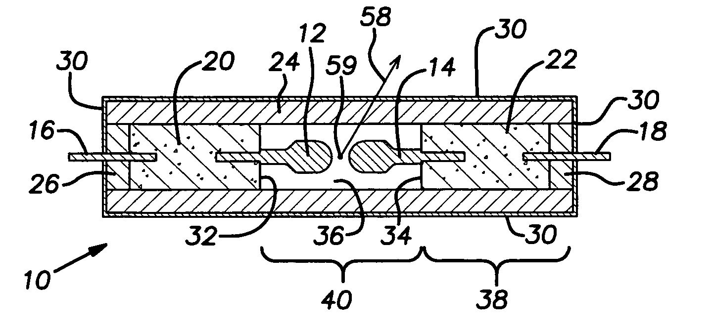
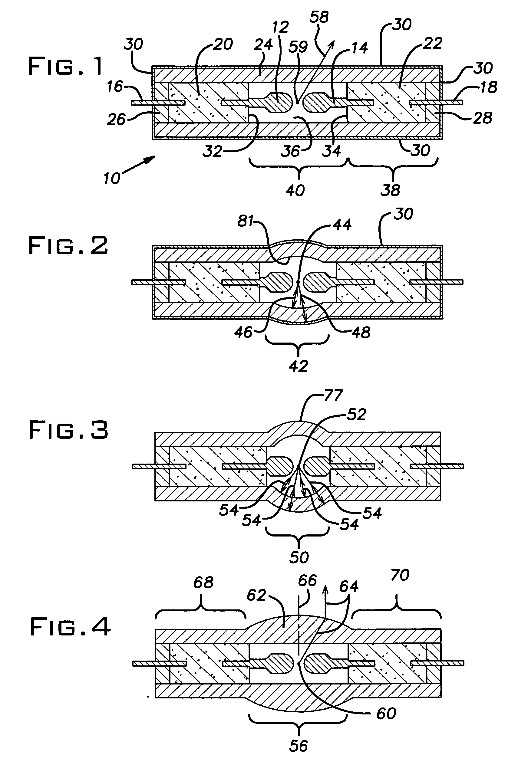
[0012] With reference to FIG. 1 there is shown in cross section a ceramic arctube 10 according to the present invention. The arctube 10 comprises electrodes 12, 14, outer leads 16,18, bodies of electrically conductive material 20, 22, a cylindrical ceramic outer shell or wall 24, and end plugs 26, 28. An anti-reflective (A / R) thin film interference coating 30 is shown disposed on the outer surface of the arctube 10. The ceramic outer shell 24 is cylindrically shaped around a longitudinal axis defined by the longitudinal axes of the outer leads 16,18 and the electrodes 12, 14 and outer shell 24 may have an outer diameter of 4-20, more preferably 6-10, mm.

[0013] The ceramic outer shell 24 is preferably poly-crystalline yttrium-aluminum-garnet (PC YAG)—Y3Al5O12; less preferably single crystal YAG; less preferably sapphir...


PUM


Abstract

A ceramic arctube preferably for a high pressure discharge lamp. The ceramic arctube can have an anti-reflection interference coating on the outside or inside surface of the bulb section of the arctube. The outside and/or inside surface of the outer wall of the bulb section of the arctube can be substantially spherical to increase efficiency. The wall thickness of the outer wall of the bulb section can be shaped to lens rays from the arc toward a preselected region of a reflector optically coupled to the arctube to increase efficiency.

Description

[0001] This application claims the benefit of U.S. Provisional Application No. 60 / 540,475 filed Jan. 30, 2004, the contents of which are incorporated herein by reference.FIELD OF THE INVENTION [0002] The present invention relates generally to ceramic arctubes used in lamps to generate light and more particularly to optical control of light from ceramic arctubes in high-pressure discharge lamps. BACKGROUND OF THE INVENTION [0003] High pressure discharge lamps produce light by ionizing a fill material such as a mixture of mercury and halogen or metal halide with an electric arc passing between two electrodes. The electrodes and the fill material are sealed within a translucent or transparent arc chamber or discharge chamber in an arctube which contains and maintains the pressure of the energized fill material and allows the emitted light to pass through it. Historically, the arctubes were formed from quartz. However, ceramic arctubes have been developed to operate at higher temperatur...

Claims


Application Information

Patent Timeline
IPC IPC(8): H01J61/30H01J61/33H01J61/35H01J61/86
CPCH01J61/35H01J61/33H01J61/302H01J61/86
Inventor ALLEN, GARY R.CHALMERS, ALAN G.DUDIK, DAVID C.VARGA, VIKTOR K.BROWN, PETER
Owner GENERAL ELECTRIC CO
Why Eureka
Try Eureka