Lithographic apparatus, measurement system, and device manufacturing method

a technology of measurement system and lithographic apparatus, applied in the direction of photomechanical exposure apparatus, printing, instruments, etc., can solve the problems of small range, high equipment cost, and complicated production of moveable objects,

Active Publication Date: 2005-08-04
ASML NETHERLANDS BV
View PDF7 Cites 145 Cited by
  • Summary
  • Abstract
  • Description
  • Claims
  • Application Information

AI Technical Summary

Benefits of technology

[0011] In a preferred embodiment, the first direction of measurement lies within a plane that is at least substantially parallel to the plane of movement. In that case, preferably the sensor head is an encoder head and the planar element is a ruler, which ruler comprises a grating. By using an encoder system comprising an encoder head and a grating, an accuracy comparable to the accuracy of an interferometer can be achieved, without having the disadvantages of an interferometer.
[0019] Preferably, the fist direction is substantially perpendicular to the second direction, and the third direction is substantially perpendicular to the plane defined by the first direction and the second direction. This significantly reduces the complexity of the algorithm that the measurement system has to process raw measurement data in order to obtain the displacements of the movable object.
[0020] Preferably, at least one measurement unit is an encoder unit, the associated sensor head being an encoder head and the associated planar element being a grating. Encoder systems are a good alternative for interferometers and / or capacitive sensors, as they reduced the disadvantages of interferometers and capacitive sensors significantly. More preferably, encoders systems are used for determining displacement of the moveable object in all six degrees of freedom.
[0021] Preferably, the planar elements of a measurement assembly are combined into a two-dimensional grating. This reduces the number of planar elements required. It is envisaged that the two-dimensional grating comprises two different groups of lines, each group comprising a plurality of mutually parallel lines, while the lines from different groups extend in different directions. Preferably, the lines of different groups intersect each other under an angle of substantially 90°. Alternatively, the two-dimensional grating is provided with a checkerboard pattern. The transitions between the relatively dark areas and the relatively light areas have the same effect as the lines of the grating described before.
[0024] In lithographic apparatus, it can occur that the displacement of the moveable object in a first translational degree of freedom is significantly larger than displacements of that moveable object in the other translational degrees of freedom. In that case, preferably the direction of measurement associated with the primary measurement units is substantially equal to the direction of the first translational degree of freedom. This increases the accuracy of the measurements.

Problems solved by technology

Interferometers are used for their accuracy, but are very expensive equipment.
The mirrors also have to be arranged under various angles, which makes the moveable object even more complex to produce.
Capacitive sensors, on the other hand, have a small range over which they can used, and their accuracy is not always sufficient.

Method used


Image

  • Lithographic apparatus, measurement system, and device manufacturing method
  • Lithographic apparatus, measurement system, and device manufacturing method
  • Lithographic apparatus, measurement system, and device manufacturing method

Examples


first embodiment

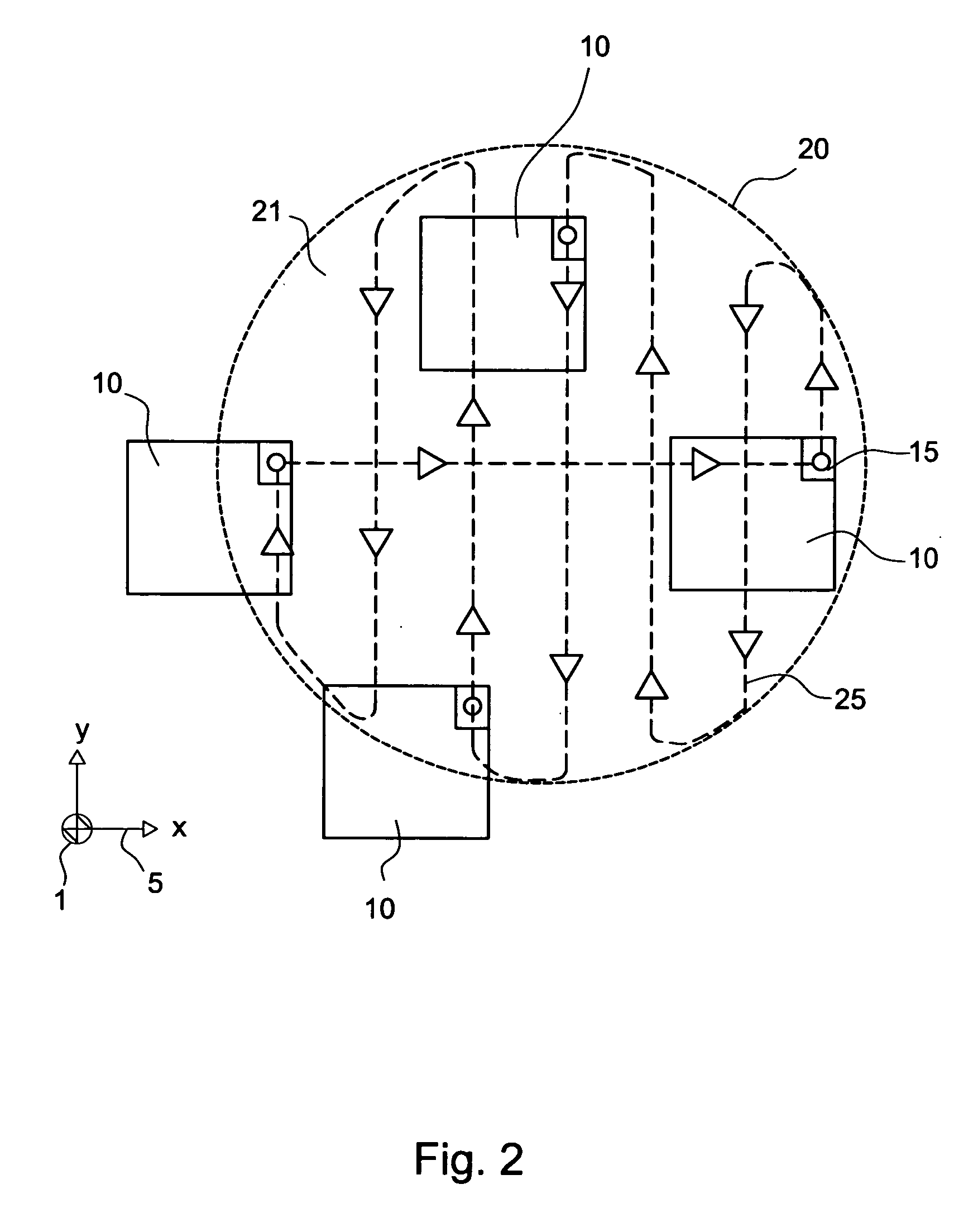
[0068]FIG. 2 schematically illustrates the first embodiment of the present invention. In FIG. 2, a base 1 is shown, relative to which moveable object 10 moves in the x-y-plane that is indicated by coordinate system 5. The x-y plane is also indicated as the “plane of movement”. The moveable object 10 follows a track in the x-y-plane. FIG. 2 illustrates this by showing the position of the moveable object 10 at four positions along the track.

[0069] The moveable object 10 comprises a reference part 15, which moves along with the moveable object 10. The track the reference part 15 of the moveable object 10 follows in the plane of movement is indicated by reference numeral 25. All movements of the reference part 15 are within area 21 of the plane of movement. Area 21 is bound by a closed contour 20.

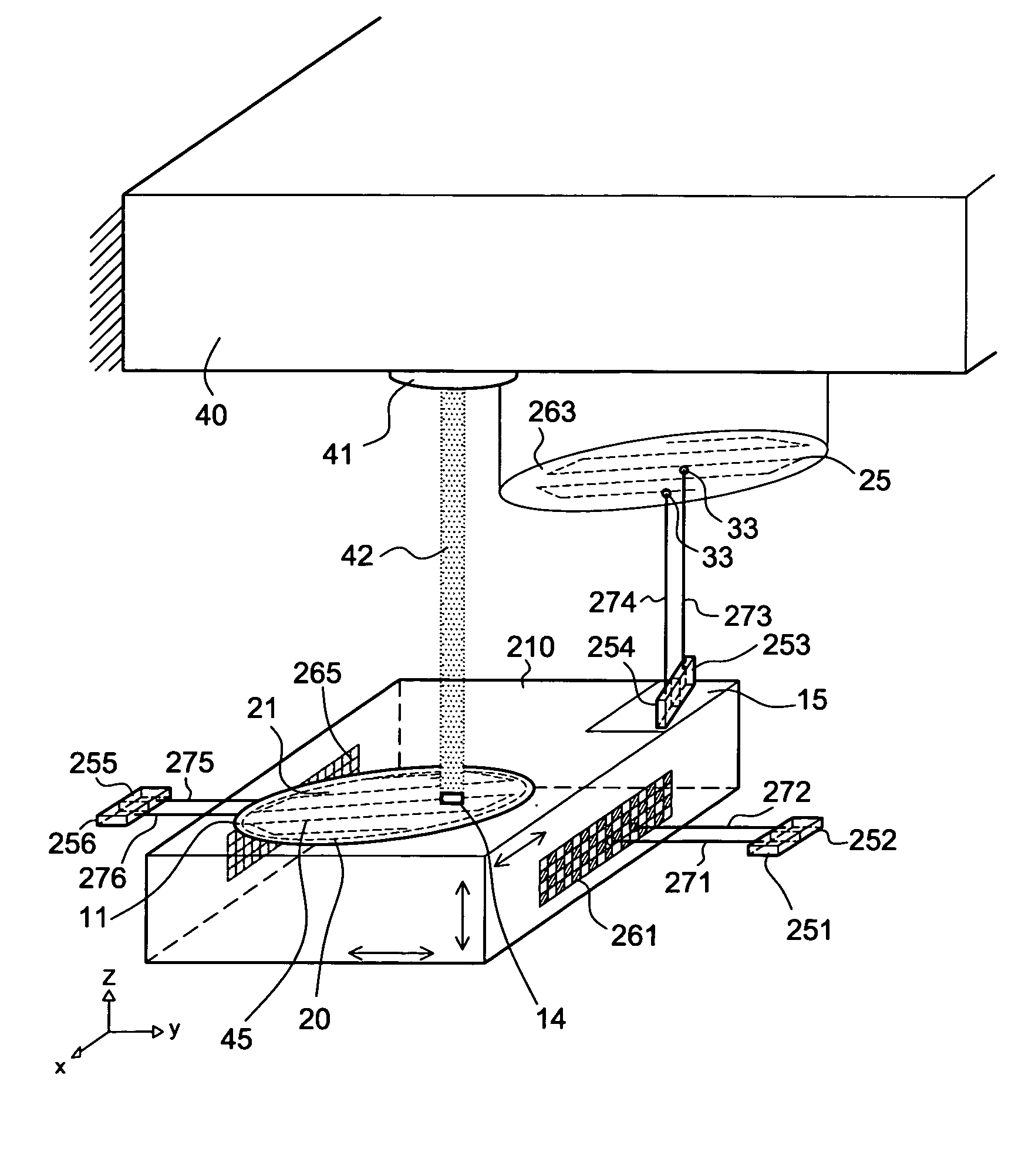
[0070]FIG. 3 schematically depicts a part of a lithographic apparatus associated with the first embodiment of the invention. In this case, moveable object 10 is a substrate table or holder 10...


PUM

PropertyMeasurementUnit
angleaaaaaaaaaa
wavelengthaaaaaaaaaa

Abstract

The invention pertains to a measurement system for measuring displacement of a moveable object relative to a base in at least a first direction of measurement, the moveable object having at least one reference part that is moveable in a plane of movement relative to the base, the actual movements of the reference part being within an area of said plane of movement that is bounded by a closed contour having a shape. The measurement system comprises a sensor head that operatively communicates with a planar element. The sensor head is mounted onto the base and the planar element being mounted onto the reference part of the moveable object or the other way around, wherein the planar element has a shape that is essentially identical to the shape of the closed contour.

Description

BACKGROUND OF THE INVENTION [0001] 1. Field of the Invention [0002] The present invention relates to a lithographic apparatus, device manufacturing method, and a measurement system. [0003] 2. Description of the Related Art [0004] A lithographic apparatus is a machine that applies a desired pattern onto a target portion of a substrate. Lithographic apparatus can be used, for example, in the manufacture of integrated circuits (ICs). In that circumstance, a patterning device, such as a mask, may be used to generate a circuit pattern corresponding to an individual layer of the IC, and this pattern can be imaged onto a target portion (e.g. comprising part of, one or several dies) on a substrate (e.g. a silicon wafer) that has a layer of radiation-sensitive material (resist). [0005] In general, a single substrate will contain a network of adjacent target portions that are successively exposed. Known lithographic apparatus include so-called steppers, in which each target portion is irradia...

Claims


Application Information

Patent Timeline
Patent Type & Authority Applications(United States)
IPC IPC(8): G03B27/42G03F7/20
CPCG03F7/70775
Inventor RENKENS, MICHAEL JOZEF MATHIJSVERHAGEN, MARTINUS CORNELIS MARIASTRUYCKEN, ALEXANDER MATTHIJSKOK, RUBEN JAN
Owner ASML NETHERLANDS BV
Why Eureka
Try Eureka