Nonlinear interferometric vibrational imaging

a vibration imaging and interferometer technology, applied in the field of nonlinear interferometer vibration imaging, can solve the problems of exposing the patient to ionizing radiation, limited in practice to a resolution over 100 microns, and high cost of diagnostic tools

Active Publication Date: 2005-08-04
THE BOARD OF TRUSTEES OF THE UNIV OF ILLINOIS
View PDF30 Cites 84 Cited by
  • Summary
  • Abstract
  • Description
  • Claims
  • Application Information

AI Technical Summary

Problems solved by technology

This method is quite versatile, and poses relatively little risk to the patient, but is limited in practice to a resolution over 100 microns.
Unfortunately, these methods have been cost prohibitive as diagnostic tools, and expose the patient to ionizing radiation.
While some biological structures produce natural fluorescence, in general externally introduced fluorescence markers must be used, which can interfere with biological processes and are often toxic.
Unfortunately, they cannot be directly excited by electromagnetic radiation of the same frequency because when they are in tissue, the surrounding water absorbs almost all of these frequencies.
This process is in practice very weak and requires large amounts of power to produce any detectable amounts of photons.
This weakness is due to the fact that the probability of a Raman excitation process to occur is proportional to the number of photons at frequency ω−Δω already present, of which there are typically few or none.
Since photons that would be emitted by Raman excitation at frequency ω−Δω are indistinguishable from the incoming radiation that stimulates them, this is not a viable technique for achieving molecular sensitivity.
Unfortunately, the penetration is usually rather low (limited to about 500 microns).
In tissues other than the eye, the imaging depth is limited by optical attenuation due to scattering and absorption.

Method used


Image

  • Nonlinear interferometric vibrational imaging
  • Nonlinear interferometric vibrational imaging
  • Nonlinear interferometric vibrational imaging

Examples


embodiment

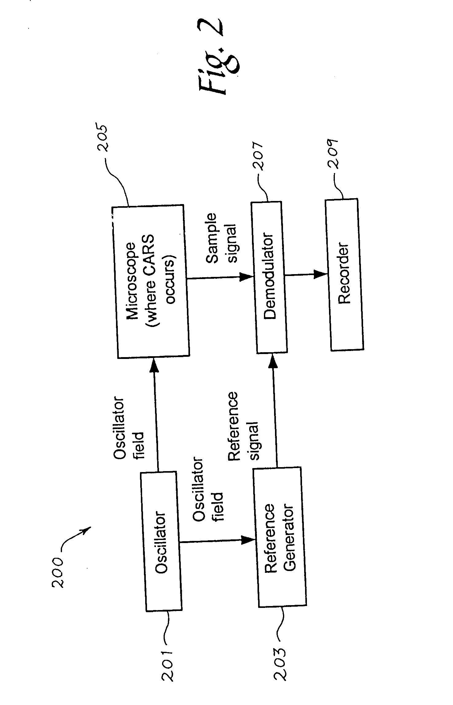
[0105] Randomness introduced into the measurement process may produce false positive indications of molecular densities, or obscure weak concentrations of molecular densities. This randomness has three sources: fluctuations in the oscillator, vibrations and air currents, and noise introduced by the photodetector.

[0106] Oscillator fluctuations are the hardest to characterize because the feedback mechanism of laser sources can produce large variations in the frequency, bandwidth, and output power of the pulses even for small perturbations of the oscillator. In addition, nonlinear processes such as self-phase-modulation, self-focusing (Kerr lensing), or continuum generation may also affect the pulse in ways that are sensitive to the power in the pulse. Therefore, it is desirable to keep fluctuations in pulse energy below a few percent, and keep frequency and bandwidth fluctuations under one percent.

[0107] Well designed state-of-the-art Ti-sapphire oscillators and regenerative amplifi...


PUM

PropertyMeasurementUnit
wavelengthaaaaaaaaaa
time scalesaaaaaaaaaa
wavelengthaaaaaaaaaa

Abstract

A method of examining a sample, which includes: exposing a reference to a first set of electromagnetic radiation, to form a second set of electromagnetic radiation scattered from the reference; exposing a sample to a third set of electromagnetic radiation to form a fourth set of electromagnetic radiation scattered from the sample; and interfering the second set of electromagnetic radiation and the fourth set of electromagnetic radiation. The first set and the third set of electromagnetic radiation are generated from a source; at least a portion of the second set of electromagnetic radiation is of a frequency different from that of the first set of electromagnetic radiation; and at least a portion of the fourth set of electromagnetic radiation is of a frequency different from that of the third set of electromagnetic radiation.

Description

CROSS REFERENCE TO RELATED APPLICATIONS [0001] The present application claims priority to U.S. Provisional application 60 / 442,300, filed Jan. 24, 2003, which is hereby incorporated by reference.FEDERALLY SPONSORED RESEARCH OR DEVELOPMENT [0002] The subject matter of this application may in part have been funded by the NASA / National Cancer Institute (Contract no. NAS2-02057). The government may have certain rights in this invention.BACKGROUND [0003] The ability to measure the three-dimensional structure of biological tissues is important, but common methods used to leave out basic information about the molecular composition and metabolic behavior of the tissue imaged. This molecular composition and metabolic behavior information may yield valuable scientific data on the behavior of biological systems, and would be of great clinical diagnostic value for finding diseases such as cancer. Much of the focus of biological and medical imaging today is to gain information about composition. ...

Claims


Application Information

Patent Timeline
Patent Type & Authority Applications(United States)
IPC IPC(8): G01J3/44G01N21/47G01N21/65
CPCG01J3/44G01N21/4795G01N2021/656G01N2021/653G01N21/65B33Y80/00
Inventor BOPPART, STEPHEN A.MARKS, DANIEL L.
Owner THE BOARD OF TRUSTEES OF THE UNIV OF ILLINOIS
Why Eureka
Try Eureka