
Reflector assemblies for luminaires

a technology of reflectors and luminaires, which is applied in the direction of semiconductor devices for light sources, fixed installations, lighting and heating apparatus, etc., can solve the problems of preventing the desired mixing of light in the far field, affecting the quality of light, so as to reduce or eliminate striations and improve quality.

Inactive Publication Date: 2005-08-04
ACUITY BRANDS
View PDF9 Cites 104 Cited by
  • Summary
  • Abstract
  • Description
  • Claims
  • Application Information

AI Technical Summary

Benefits of technology

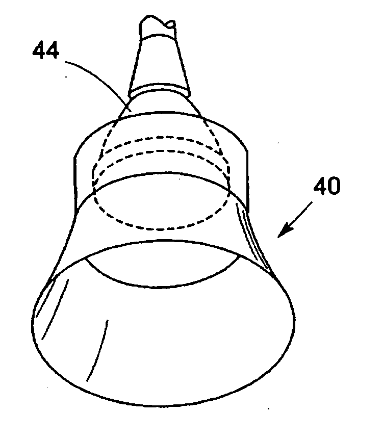
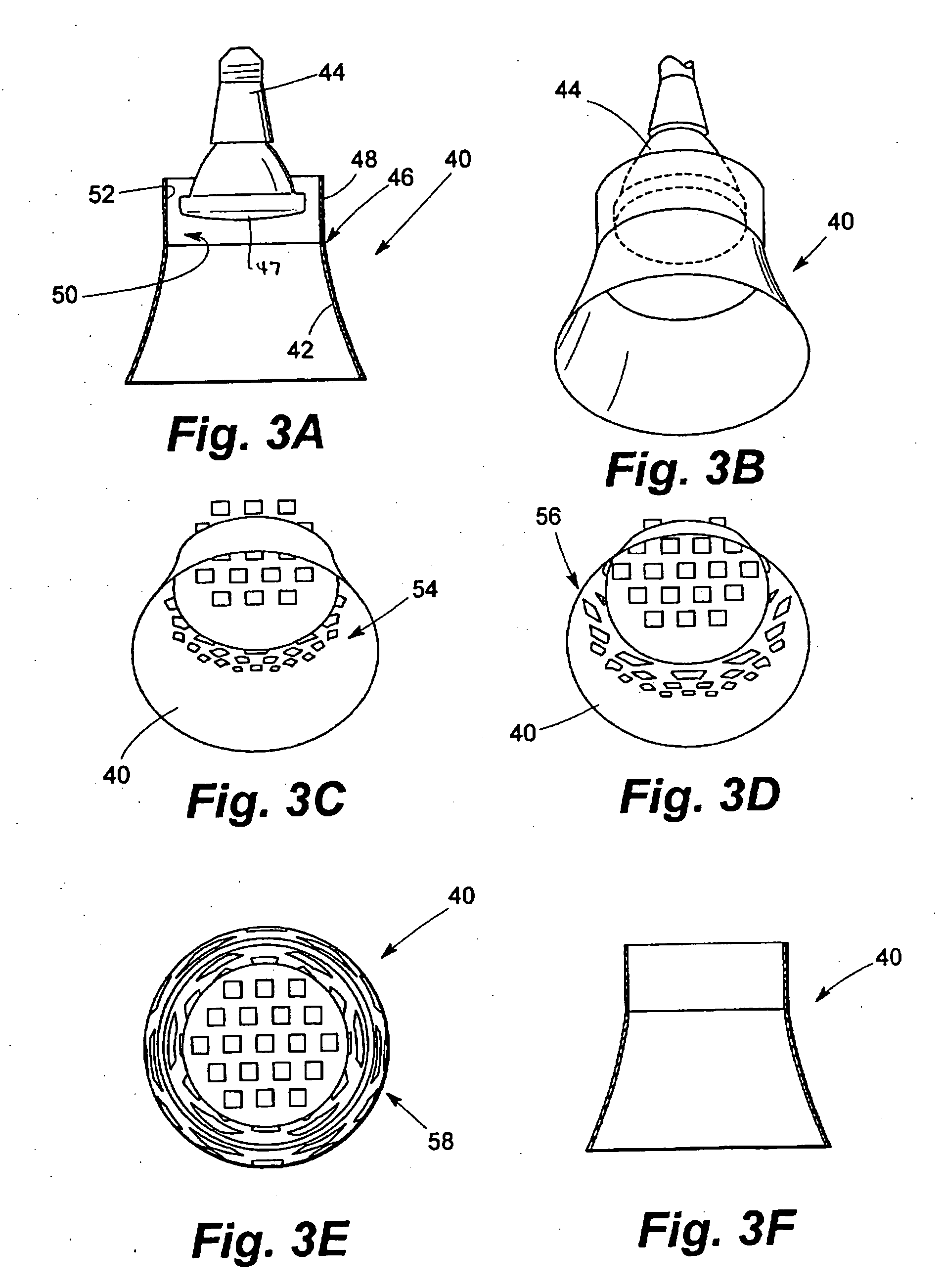
[0009] Applicants have discovered that the conventional reflector used in a luminaire, which is concave and often parabolic, interacts with the near-field light pattern of a PAR lamp resulting in an undesirable light pattern in the far field. In accordance with the invention, several embodiments of an optical arrangement are provided that are particularly suited for downlighting applications, yet useful also in luminaires intended for other applications. In downlighting applications and particularly recessed downlighting applications, the optical arrangements of the invention take the form of a reflector that is preferably conical (i.e., a revolved straight line) but also divergent (i.e., a revolved convex curve), and used in concert with a PAR lamp or other lamp having a lenticular pattern, that is, a “dimpled” lens face or similar pattern. A particularly effective reflector is a conical reflector that takes the form of the frustum of a cone. Reflectors as thus described are preferably spaced from the PAR or similar lamp, the lens face of the lamp being separated from upper portions of the reflector by a gap preferably occupied by an annular element that is not reflective and is preferably black to absorb incident light. The annular element separates the lamp from the upper part of the reflector thereby to improve the performance of the optics of a luminaire so configured.
[0012] This invention contemplates the use of reflective surfaces used in combination with a PAR or similar lamps whereby the reflective surfaces cause light rays incident thereon not to converge as occurs with concave reflective surfaces such as parabolic surfaces as are commonly employed in downlighting and other applications, such parabolic surfaces essentially providing magnified virtual images of the spatial elements of the incident light pattern. A particular reflector useful according to the invention is referred to herein for simplicity as a “conical” reflector, such a reflector having reflective surfaces in the shape of a frustum of a cone. Luminaires utilizing PAR lamps, or similar lamps, find particular utility through incorporation of reflectors having neutral or diverging reflective surfaces to include convex and conical reflectors according to the invention, such luminaires providing improved light patterns whether the lamping employed takes the form of incandescent or HID versions of PAR lamping such as PAR 20, 30 and 38 lamps. It is to be understood that neutral or diverging convex reflectors (or under appropriate circumstances a concave diverging reflector) can also be employed according to the invention and are encompassed within the definition of neutral or diverging reflectors as defined herein. Combinations including a matte, black annulus, such as in the form of a snoot, with a divergent or conical reflector and a PAR lamp results in luminaires such as downlighting luminaires that substantially improve the characteristics of light emanating from such luminaires through glare reduction, reduction or elimination of striations, and improvement of the appearance of scallops apparent on surfaces of an environmental space with which such luminaires are used. The annulus not only separates the reflector and the lamp physically but also improves reflector flash performance and produces a more clear projected beam: It is also to be understood that the use of the terms “divergent reflective surfaces”; “diverging reflective surfaces”; a “divergent reflector” or a “diverging reflector” encompasses a conical reflector or conical reflecting surfaces as well as convex and other surfaces that are substantially diverging with respect to their reflection of incident light rays.
[0017] It is a further object of the invention to provide downlighting luminaires utilizing light sources such as PAR lamps and the like that are configured with a divergent or conical reflector preferably spaced from lens faces of such light sources, gaps thus formed therebetween that are each preferably occupied by a band-like annular element preferably having a matte finish of relatively dark coloration such as black, the downlighting luminaires thus configured preferably being recessed in ceilings or walls of environmental spaces and producing beams of improved quality characterized by reduction or elimination of striations on surfaces of such spaces illuminated by such beams.

Problems solved by technology

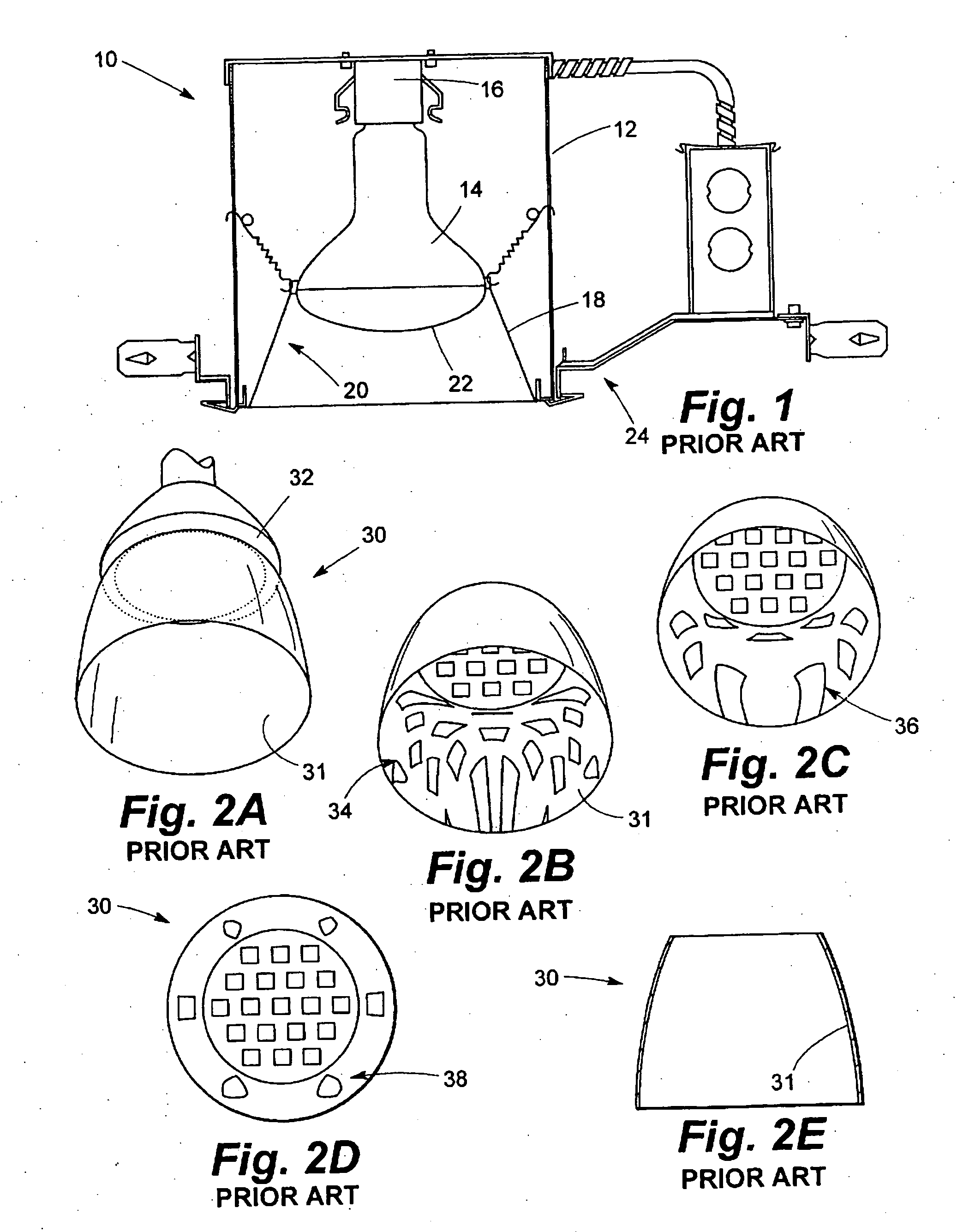
Applicants have discovered that the conventional reflector used in a luminaire, which is concave and often parabolic, interacts with the near-field light pattern of a PAR lamp resulting in an undesirable light pattern in the far field.
The interaction of the light from these elements with a converging reflector, however, prevents the desired mixing of the light in the far field.
The light from the individual elements on the face of the PAR lamp, therefore, do not mix properly in the far field because the field of view of each element is too small to overlap appropriately with the light from the other elements.

Method used


Image

  • Reflector assemblies for luminaires
  • Reflector assemblies for luminaires
  • Reflector assemblies for luminaires

Examples


Embodiment Construction

[0039] Referring now to the drawings and particularly to FIG. 1, a prior art downlighting luminaire 10 includes a housing 12 within which an R30 lamp 14 is mounted by a socket 16. A reflector 18 having reflective surfaces 20 is formed as a frustum of a cone. Lower portions of the lamp 14 extend below the top of the reflector and into the space within the reflector 18 through open upper portions of reflector 18. Lens face 22 of the lamp 14, thus, lies substantially within the space defined by the reflector 18 and is below the upper edges of the reflector 18. The downlighting luminaire 10 is usually mounted in a recessed location within a ceiling or the like (not shown) by a conventional mounting frame shown generally at 24. The luminaire 10 is seen to utilize a conically shaped reflector 18 in combination with an R lamp. Because the R lamp has a diffuse coating on exit face 22, the light pattern is generally uniform in the near field and does not give rise to the non-uniformities inh...


PUM


Abstract

Downlighting luminaires equipped with particular light sources such as PAR lamps, light emitting diode (LED) arrays and the like, are equipped with reflectors that do not converge light rays incident thereon from the light source. Downlighting luminaires configured according to the invention reduce or eliminate undesirable beam striations on horizontal surfaces and “busy” scallops on vertical surfaces with improvement of reflector flash performance. Particular reflectors have divergent reflective surfaces or conical surfaces, the reflectors preferably being optically separated from a face of the lamp such as by means of a matte black annulus or “snoot” disposed between the lamp face and opposing edges of the reflector.

Description

BACKGROUND OF THE INVENTION [0001] 1. Field of the Invention [0002] The invention relates generally to downlighting luminaires and, particularly, to such luminaires utilizing light sources such as PAR lamps, which produce unwanted beam striations and the like when used with conventional parabolic reflectors. [0003] 2. Description of the Prior Art [0004] Downlighting luminaires are used in a wide variety of configurations for general lighting, task lighting, accent lighting, emergency lighting, and the like. By being recessed in a ceiling, or otherwise mounted such as in a wall or carried by a framework spaced from a true ceiling, downlighting luminaires are desirably unobtrusive. Downlighting luminaires are designed for use with a variety of light sources including incandescent, fluorescent, and high-intensity-discharge lamping, to list but a few. Quite often, a given environmental space is provided with downlighting luminaires having different light sources, and it is desirable for...

Claims


Application Information

Patent Timeline
IPC IPC(8): F21S8/02F21V7/04
CPCF21S8/026F21Y2105/001F21Y2101/02F21V7/04F21Y2105/10F21Y2115/10
Inventor WEGNER, SCOTT
Owner ACUITY BRANDS
Learn More