Lan-to-lan VOIP system and related user interface

a technology of voice over internet protocol and user interface, applied in the field of lan-to-lan voip system, can solve the problem of high price of static ip address, and achieve the effect of friendly user interfa

Inactive Publication Date: 2005-08-04
TRANSPACE TECH
View PDF12 Cites 41 Cited by
  • Summary
  • Abstract
  • Description
  • Claims
  • Application Information

AI Technical Summary

Benefits of technology

[0009] It is an advantage of the claimed invention that the LAN-to-LAN VoIP system and related user interface can connect a plurality of LANs to one another. In each LAN, the IP-based extensions can access the trunk lines, and dial to the PBX as well as the normal telephones in an extension-like way in the same LAN. Additionally, if the IP-based extension in one LAN dials to the IP-based extensions, the normal telephones, or PSTN in another LAN, the voice packets transmitted from the IP-based extension are transmitted to the NPBX host at first. Only the hosts of each LAN need static IP addresses such that the static IP addresses are mostly reduced in the LAN-to-LAN VoIP system. In addition, the functional keys, used in the IP-based extension for connecting to the trunk lines directly, provide users with a more friendly user interface.

Problems solved by technology

Not only are the static IP addresses expensive, but also a static IP address is needed in the VoIP system 10 for each normal telephone or PSTN.

Method used


Image

  • Lan-to-lan VOIP system and related user interface
  • Lan-to-lan VOIP system and related user interface
  • Lan-to-lan VOIP system and related user interface

Examples


first embodiment

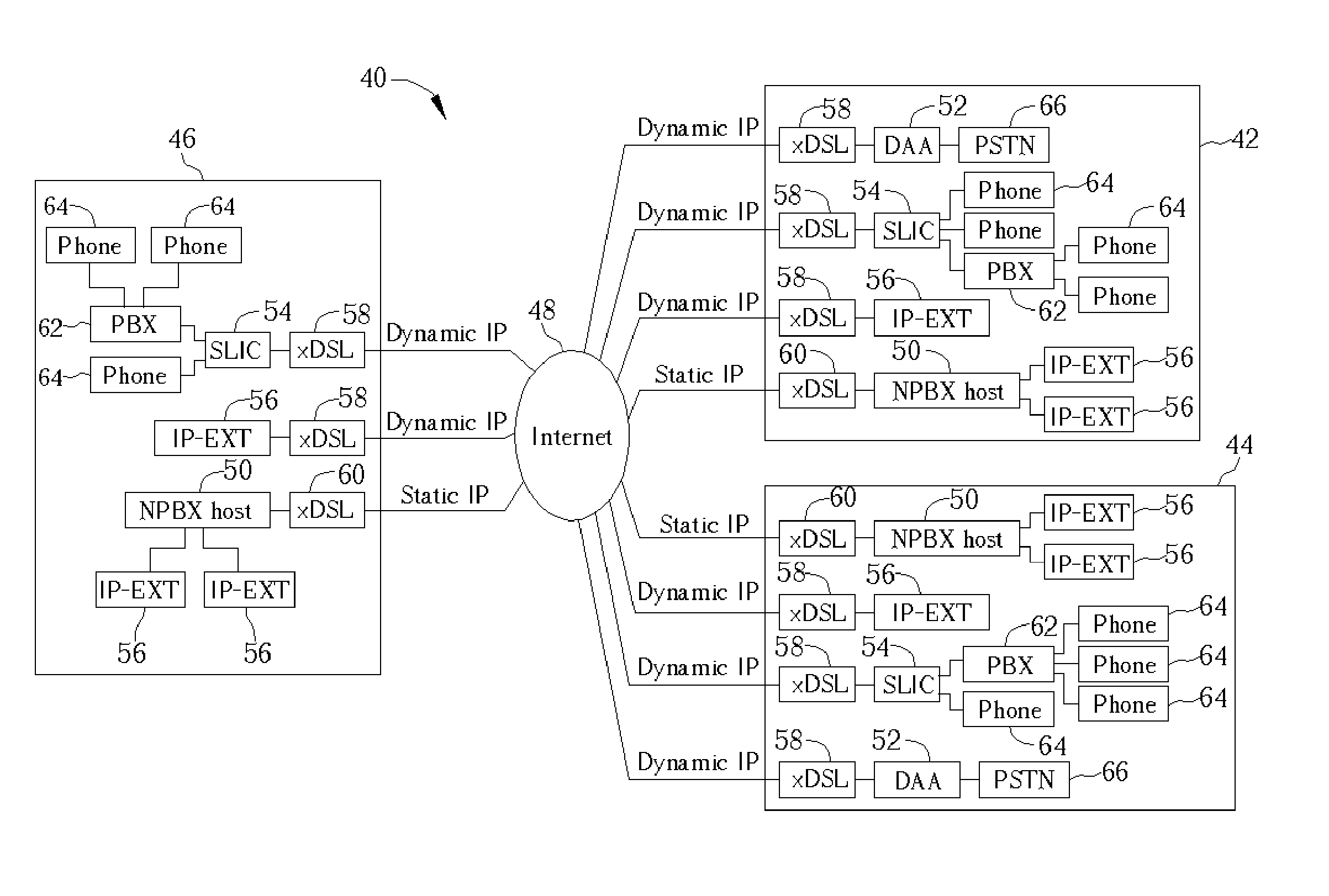
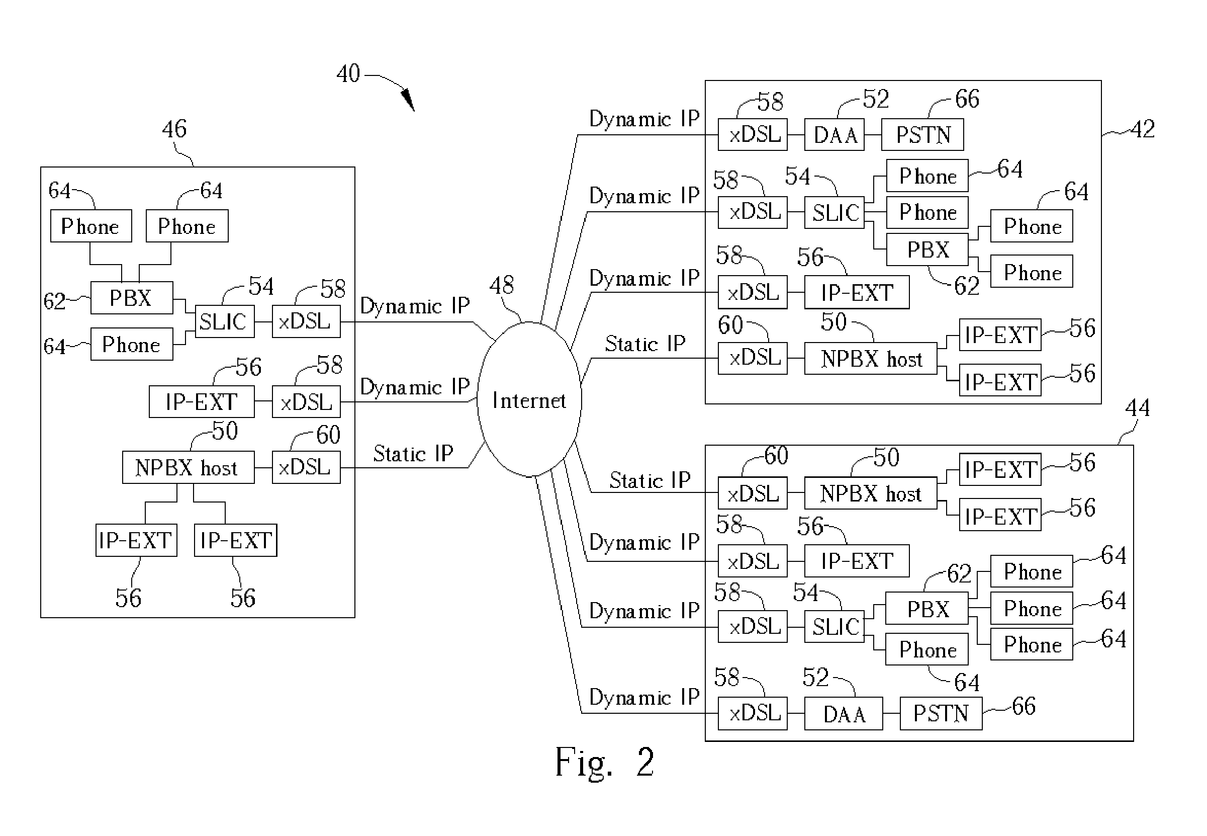
[0015] Please refer to FIG. 2. FIG. 2 is a functional block diagram of a LAN-to-LAN VoIP system 40 according to the present invention. The LAN-to-LAN VoIP system connects a plurality of LANs 42, 44, and 46 via the Internet 48. Each of the LANs 42, 44, and 46 has a respective network private branch exchange (NPBX) host 50 connected to the Internet 48 through a respective Internet connection 60. The Internet connection 60 may be an xDSL connection or other broadband Internet connection, which provides a static IP address to the NPBX host 50.

[0016] Additionally, each of the LANs 42, 44, and 46 comprises a plurality of communication modules, which connect a plurality of local telephone systems to the Internet 48 through a plurality of Internet connections 58. The Internet connection 58 may be an xDSL connection or other broadband Internet connections, which provide dynamic IP addresses to the communication modules.

[0017] The communication modules are data access arrangement (DAA) modul...

second embodiment

[0019] All connections between the DAA modules 52, the SLIC modules 54, the IP-based extensions 56, and the Internet 48 are wired connections in FIG. 2. Please refer to FIG. 3. FIG. 3 is a functional block diagram of a LAN-to-LAN VoIP system 70 according to the present invention. The LAN-to-LAN VoIP system 70 is similar to the LAN-to-LAN VoIP system 40, and the same reference numbers will be used to refer to the same parts. Instead of using wired connections to connect local telephone systems, the LAN-to-LAN VoIP system 70 utilizes IP sharing 78 and access points 80 to wirelessly connect the DAA modules 52, the SLIC modules 54, the IP-based extensions 56, and the Internet 48. As shown, the DAA modules 52, SLIC modules 54, and the IP-based extensions 56 can all communicate with the access point 80 to connect the Internet 48 using at least one of the many IEEE 802.11x protocols. Besides, the IP-based extensions 56 can communicate with the access point 80 to connect the NPBX 50 using a...


PUM


Abstract

A LAN-to-LAN VoIP system and related user interface. The VoIP system comprises a first LAN and a second LAN. The first LAN comprises a first local telephone system, a first communication module, a first IP-based extension, and a first host. The second LAN comprises a second local telephone system, a second communication module, a second IP-based extension, and a second host. Each communication module connects each local telephone systems to the Internet through a respective dynamic IP address, each IP-based extension is connected to the Internet through another dynamic IP address, and each host is connected to the Internet through a respective static IP address. Each IP-based extension can dial to the local telephone system directly in the same LAN or dial to the host followed by the local telephone systems across LAN. The user interface, used in each IP-based extension, comprises a first functional key for dialing to the trunk lines of the first local telephone system and a second functional key for dialing to the trunk lines of the second local telephone system.

Description

BACKGROUND OF INVENTION [0001] 1. Field of the Invention [0002] The present invention relates to a Voice over Internet Protocol (VoIP) system and related user interface, and more particularly, to a LAN-to-LAN VoIP system with the related user interface which connects local area networks (LAN) to one another. [0003] 2. Description of the Prior Art [0004] With the popularity of Internet connections, VoIP systems are developed to transmit voice efficiently over the Internet. Please refer to FIG. 1. FIG. 1 is a functional block diagram of a VoIP system 10 according to the prior art. The VoIP system 10 connects a plurality of voice gateways 14, and 16 through respective Internet connections 12. [0005] The Internet connections 12 may be xDSL connections or other broadband Internet connections, which provide static IP addresses to the voice gateways 14 and 16. The voice gateways 14 are electrically connected to a private branch exchange (PBX) 22 and a normal telephone 24 with FXS interface...

Claims


Application Information

Patent Timeline
Patent Type & Authority Applications(United States)
IPC IPC(8): H04L12/46H04L12/56H04L12/66H04L29/12H04M7/00H04M11/06
CPCH04L12/4604H04L29/12311H04M7/009H04L65/1073H04M7/006H04L61/2084H04L61/5084
Inventor CHEN, HENG-CHIEN
Owner TRANSPACE TECH
Why Eureka
Try Eureka