
Wildfire protection

a technology for protecting wildfires and destroying structures, applied in the field of fire and thermal energy protection, can solve the problems of not being able to adequately move each and every one, and the problem of protecting fixed structures for mankind, and achieve the effect of inhibiting degradation and/or destruction

Inactive Publication Date: 2005-08-04
KIMENER R PETER
View PDF17 Cites 5 Cited by
  • Summary
  • Abstract
  • Description
  • Claims
  • Application Information

AI Technical Summary

Benefits of technology

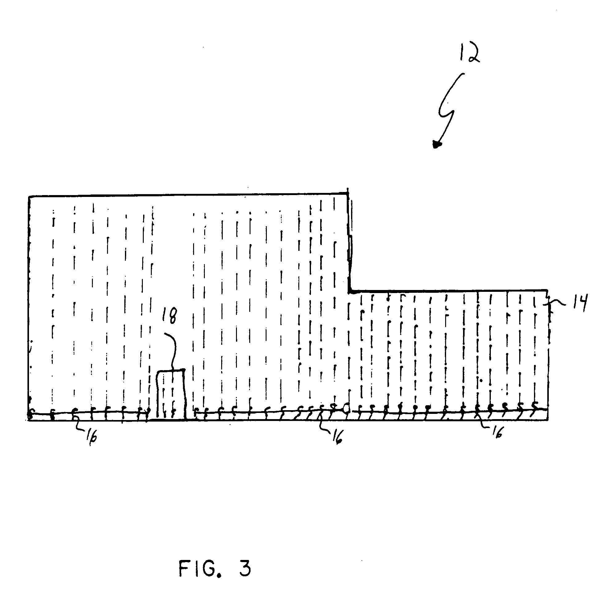
The present invention provides a protective barrier for structures, vehicles, trailers, boats, and other assets that can be exposed to fire and high temperatures. The protective barrier is a blanket that can be selectively deployed to shield the asset from the threat of fire and thermal energy. The blanket includes a fire resistant layer and a thermal energy shield layer that work together to reduce the risk of damage to the asset. The protective barrier can be mounted to the ground, the asset itself, or a support structure to maintain its position. The invention also includes a method for deploying the protective barrier and a protective apparatus for isolating protectable assets from fire and thermal energy.

Problems solved by technology

This is particularly the case where water shortages do not readily permit residential housing owners to retard the oncoming fires or the owners are forced to evacuate from the residence in light of the veracity of the oncoming fires.
Likewise, fast moving wildfires may not make it possible to adequately move each and every one of the mobile assets that may be located within a storage building or otherwise on a property in the path of a wildfire.
In sum, protecting fixed structures has been a problem for mankind throughout his habitation of earth.

Method used


Image

  • Wildfire protection
  • Wildfire protection
  • Wildfire protection

Examples


Embodiment Construction

[0024] The exemplary embodiments of the present invention are described and illustrated below to encompass apparatuses and associated methods to protect assets from degradation and / or destruction that might otherwise result from unprotected exposure to a fire or a high temperature thermal energy source. Of course, it will be apparent to those of ordinary skill in the art that the preferred embodiments discussed below are exemplary in nature and may be reconfigured without departing from the scope and spirit of the present invention. However, for clarity and precision, the exemplary embodiments as discussed below include optional steps and features that one of ordinary skill should recognize as not being a requisite to fall within the scope and spirit of the present invention.

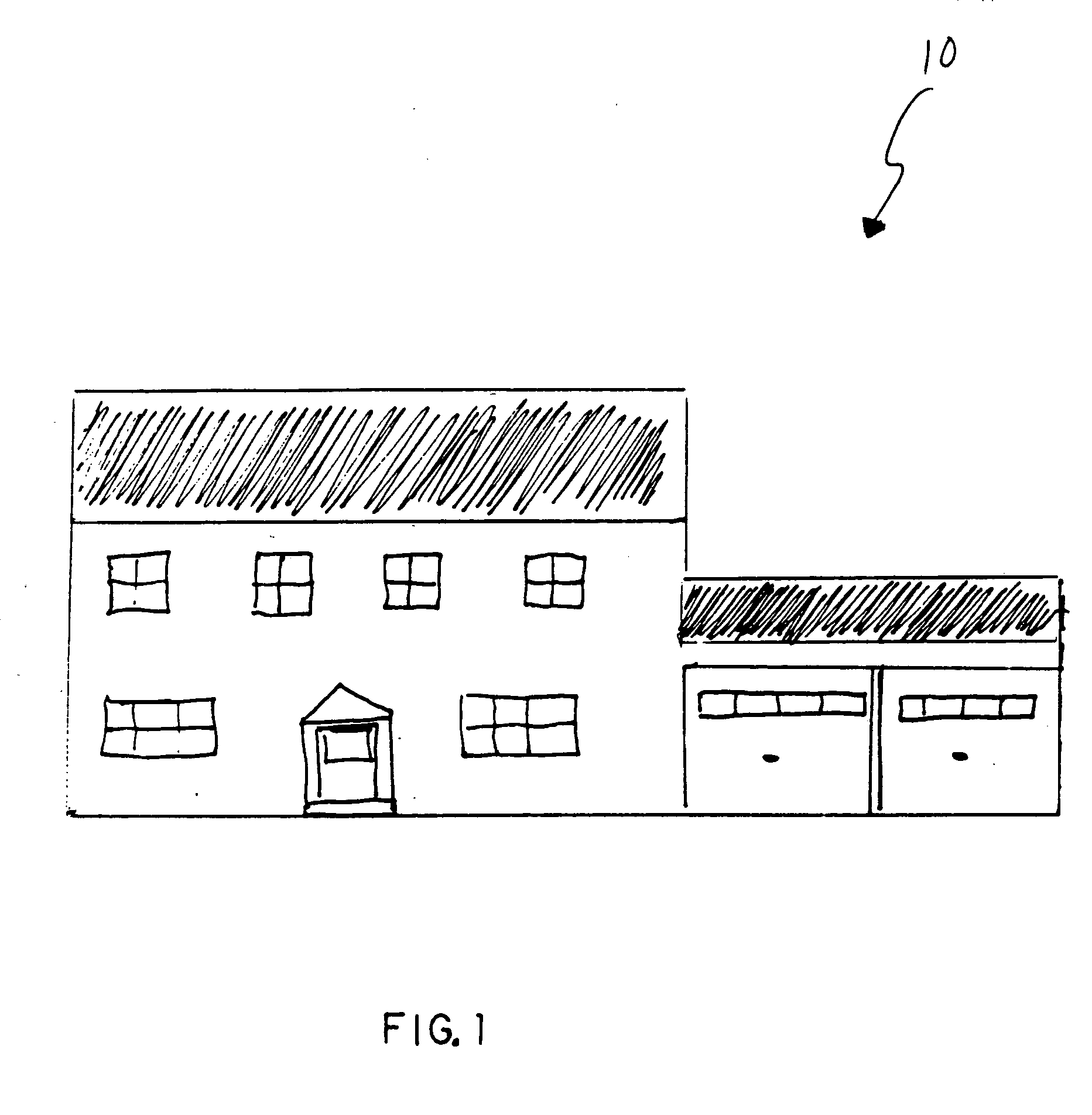
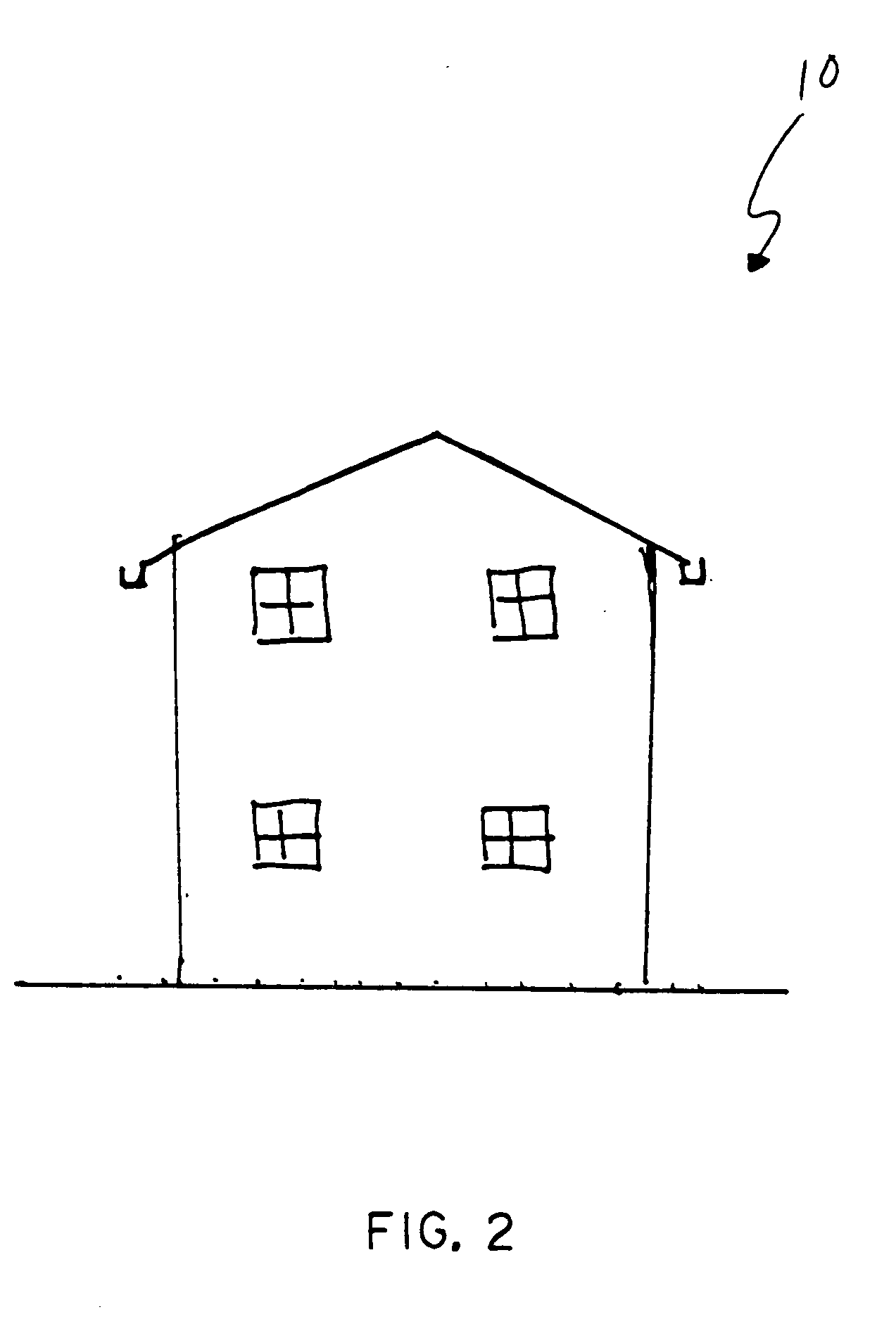
[0025] Referencing FIGS. 1 and 2, an exemplary structure 10 may represent a residential, commercial, industrial, institutional, or other building. For purposes of explanation only, the exemplary structure 10 di...


PUM

PropertyMeasurementUnit
thermal energyaaaaaaaaaa
fire resistantaaaaaaaaaa
energyaaaaaaaaaa

Abstract

A method of protecting an asset from destruction resulting from exposure to at least one of fire and thermal energy comprising: (a) identifying a pending threat capable of at least substantially destroying an asset by exposure to at least one of fire and thermal energy; (b) deploying a barrier, that includes a fire resistant layer and a thermal energy reflective layer, to separate the asset from the pending threat; and (c) securing the barrier to at least one of the ground, the asset itself, and a support structure; (d) wherein the act of securing the barrier is operative to retain at least one of the fire resistant layer and the thermal energy shield layer between the asset and the pending threat.

Description

CROSS REFERENCE TO RELATED APPLICATIONS [0001] This application claims the benefit of U.S. Provisional Patent Application Ser. No. 60 / 534,564, filed Jan. 6, 2004, and entitled “WILDFIRE PROTECTION,” the disclosure of which is incorporated herein by reference.BACKGROUND [0002] 1. Field of the Invention [0003] The present invention is directed to fire and thermal energy protection for structures, vehicles, trailers, boats, and other assets, that are or may become exposed to a fire or a high temperature thermal energy source. More specifically, the present invention is directed to a fire and thermal energy protective barrier that may be selectively deployed in proximity to an asset to inhibit degradation and / or destruction that might would otherwise result from unprotected exposure to a fire or a high temperature thermal energy source. [0004] 2. Background of the Invention [0005] Each year hundreds of acres of land and the contents thereof are consumed by wildfires. A property owner ge...

Claims


Application Information

Patent Timeline
Patent Type & Authority Applications(United States)
IPC IPC(8): B27N9/00B32B5/02B32B5/26B32B7/02B32B27/04
CPCB32B7/02Y10T442/668Y10T442/3382Y10T442/259Y10T442/3707Y10T442/3472Y10T442/659Y10T442/654B32B17/02B32B15/20B32B15/14B32B2307/3065B32B2307/306B32B2605/08B32B5/08B32B2419/00
Inventor KIMENER, R. PETER
Owner KIMENER R PETER
Learn More