Safety syringe

a safety syringe and syringe technology, applied in the field of syringes, can solve the problems of increased failure rate, needle deflection in local anesthetic injections, and no dental syringe with these features, so as to reduce the force needed to penetrate the patient's tissue, reduce the needle deflection, and enhance the safety of the operator

Inactive Publication Date: 2005-08-04
HOCHMAN MARK N
View PDF26 Cites 27 Cited by
  • Summary
  • Abstract
  • Description
  • Claims
  • Application Information

AI Technical Summary

Benefits of technology

[0018] This syringe described herein overcomes the known disadvantages of existing syringes. It is a capable of both intermittent locking during use as well as permanent locking after use. In addition, an optional design configuration utilizes a single ended medical Luer-lock needle in combination with a standard local anesthetic cartridge enhancing the safety to the operator. An additional benefit of this device is an innovative design element in the barrel of the syringe that guides the needle into translation / rotation during injection, resulting in the reduction of force needed to penetrate the patient's tissue and also reduces needle deflection. Needle deflection in local anesthetic injections has been associated with increased failure rates. This same feature of simultaneous rotation / translation of needle will also result in a reduced amount of force to remove the needle from the patients' tissues, once again aiding in the safety and comfort to both the operator and patient. An auto-aspiration design is an innovative safety element in one of the potential designs of this device. The inclusion of this feature ensures greater safety for patients during the use of this device. Currently, no dental syringe is available with these features.

Problems solved by technology

Needle deflection in local anesthetic injections has been associated with increased failure rates.
Currently, no dental syringe is available with these features.

Method used


Image

  • Safety syringe
  • Safety syringe
  • Safety syringe

Examples


Embodiment Construction

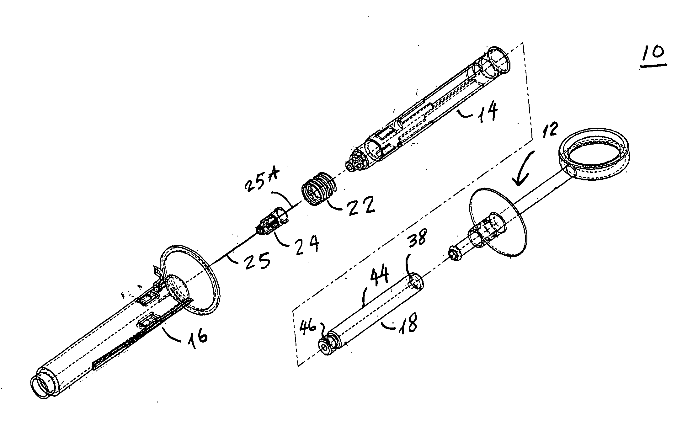
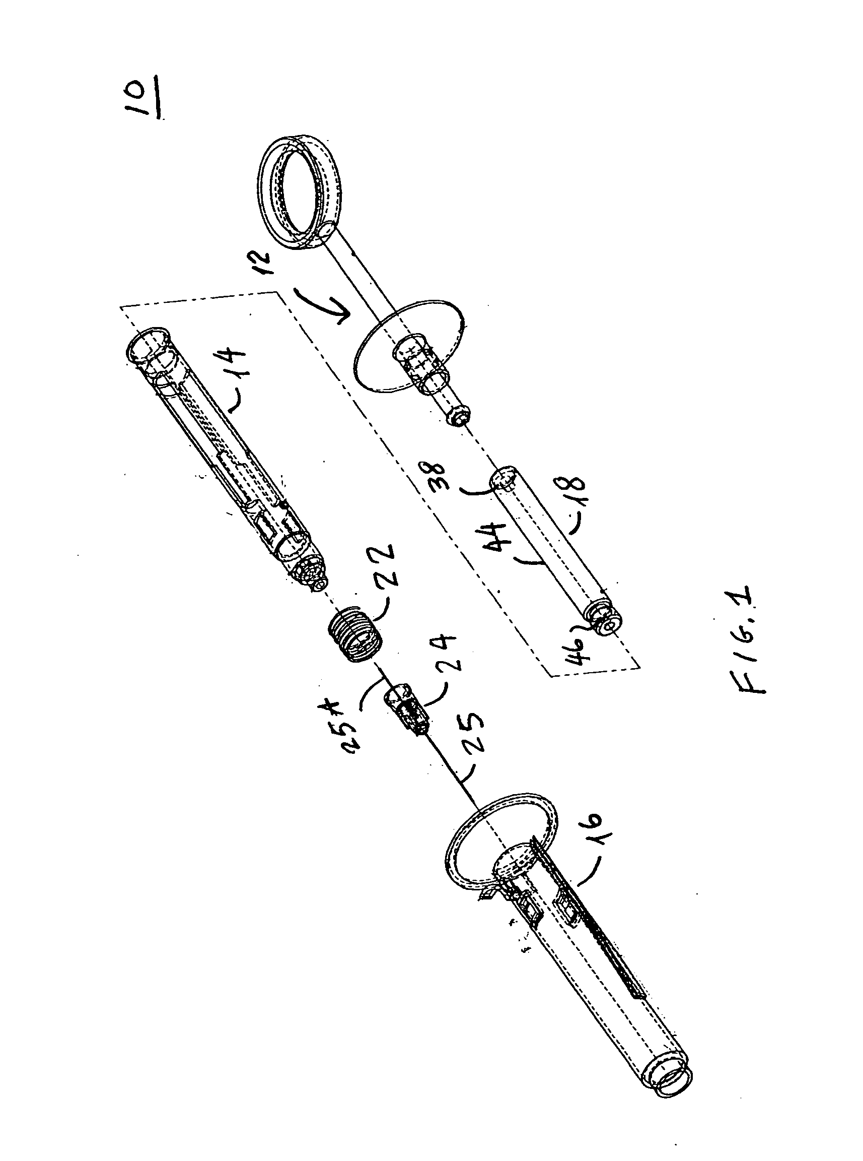
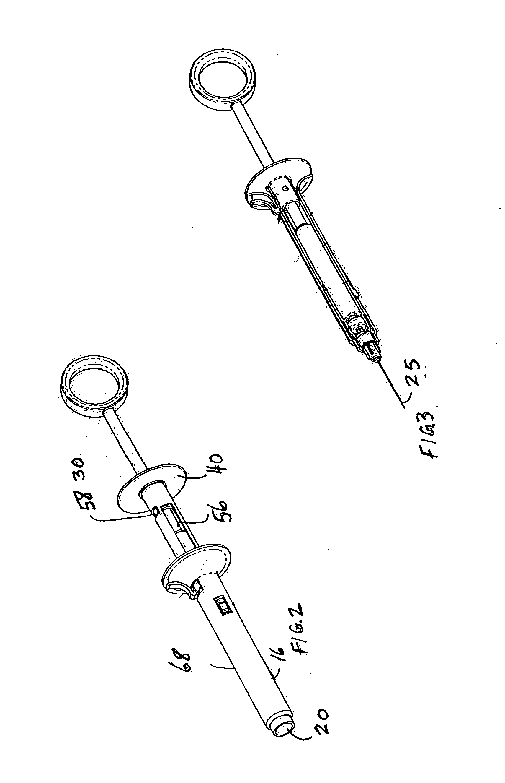
[0040] Referring first to FIGS. 1-10, a safety syringe 10 constructed in accordance with this invention includes a plunger assembly 12, an inner sleeve 14, and an outer sleeve 16 terminating at its distal end with an aperture 20. Briefly, a cartridge 18 filled with a desired liquid is inserted into the inner sleeve 14 and the inner sleeve 14 is the closed by inserting therein an end of the plunger assembly 12. A coil spring 22 is positioned on one end of the inner sleeve 12, a standard dental needle assembly 24 having a needle tip 25 is attached to the inner sleeve as shown in FIG. 2. The syringe 10 is then operated by forcing the inner sleeve 12 and its cartridge 18 through the outer sleeve 14 so that a portion of the needle assembly 24 exits through aperture 20. As the needle assembly exits through the aperture, the liquid within the cartridge is expressed through the needle and therefore the injection may be started as soon as the needle tip appears through the aperture. Preferab...


PUM

PropertyMeasurementUnit
angleaaaaaaaaaa
angleaaaaaaaaaa
flexibleaaaaaaaaaa

Abstract

A safety syringe is formed of an inner sleeve receiving a cartridge with liquid, an outer sleeve through which said inner sleeve is telescopically reciprocated, and a plunger assembly that is attached to the inner sleeve and used to eject the liquid. The needle is mounted on a front end of the inner sleeve and in a retracted position is wholly contained within the outer sleeve while in a protracted position the needle is exposed so that it can be used for an injection. Advantageously, in one embodiment, the inner sleeves can rotate with respect to each other causing the needle to rotate both when the needle is extended and when is retracted into the outer sleeve. Another feature of the invention is that in one embodiment the inner sleeve has an internal puncture member for puncturing the cartridge. Therefore, instead of a dental needle with two sharp tips, a standard needle with a single tip and a Luer connection may be used.

Description

RELATED APPLICATIONS [0001] This application is a continuation-in-part of patent application Ser. No. 10 / 209,415 filed Jul. 31, 2002, which is a divisional application of patent application Ser. No. 09 / 506,484 filed Feb. 17, 2000 (now U.S. Pat. No. 6,428,517 issued Aug. 6, 2002) and which claimed priority to provisional applications Ser. No. 60 / 133,397 filed May 10, 1999 and Ser. No. 60 / 173,374 filed Dec. 28, 1999, all incorporated herein by reference.BACKGROUND OF THE INVENTION [0002] A. Field of Invention [0003] This invention pertains to a syringe used to inject a therapeutic fluid into human or animal tissues, and more particularly to a syringe that includes a needle movable along a longitudinal axis, which needle is optionally rotating about said axis as well. Importantly, prior to and immediately after the injection, the needle is disposed in a protective sleeve that prevents needle sticks. Preferably, after an injection is completed, a permanent locking mechanism is activated...

Claims


Application Information

Patent Timeline
Patent Type & Authority Applications(United States)
IPC IPC(8): A61M5/00A61M5/32B01J19/00C40B60/14
CPCA61M5/00A61M2205/586A61M5/322A61M5/3232A61M5/3257A61M5/3271A61M5/3287A61M5/422A61M2005/2407A61M2005/2492A61M2005/3139A61M2005/3228A61M2005/3289A61M2205/583B01J19/0046B01J2219/00313B01J2219/00364B01J2219/00389B01J2219/00394B01J2219/00495B01J2219/00585B01J2219/00698B01J2219/00707B01J2219/0072C40B60/14A61M5/24
Inventor HOCHMAN, MARK N.
Owner HOCHMAN MARK N
Why Eureka
Try Eureka