High impedance fault detection

a fault detection and high impedance technology, applied in non-electric variable control, process and machine control, instruments, etc., can solve problems such as high impedance faults, serious public safety hazards, and risk of arcing ignition of fires

Active Publication Date: 2005-08-04
ABB INC
View PDF14 Cites 48 Cited by
  • Summary
  • Abstract
  • Description
  • Claims
  • Application Information

AI Technical Summary

Benefits of technology

[0023] determining a presence of a high impedance fault using a decision means, wherein the decision means determines a high impedance fault if any two or more of the independent outputs are indicative that an associated one of the plurality of high fault detection means has detected a high impedance fault condition.

Problems solved by technology

High impedance faults result when an energized primary conductor comes in contact with a quasi-insulating object, such as a tree, a structure or equipment, a pole crossarm, or falls to the ground.
The significance of these hard to detect faults is that they represent a serious public safety hazard as well as a risk of arcing ignition of fires.
High impedance faults, are typically found on distribution circuits, results in very little, if any, current.
High impedance faults do not pose a threat to equipment and by their nature they can not be detected with conventional overcurrent devices.
Nonetheless, the dangers of a downed conductor are obvious to all.
Possibility of fire, property damage, and someone coming into contact with the live conductor are some of the major concerns.
Also, legal issues in promising a comprehensive solution may be very costly for manufacturers (e.g., liability issues).
For example, tripping the breaker following high impedance fault detection is not a clear cut choice.
While the high impedance fault is a danger, tripping the feeder unnecessarily will create new hazards by de-energizing homes, traffic signals, offices, etc.
The effects of incorrectly determining a high impedance fault will have economic and legal ramifications.
However, high impedance fault detection has not been possible in the past and realistic detection algorithms are not anticipated that can detect 100% of all downed conductors, while having 100% security against misoperation.
Although the algorithm was field tested, its performance limited its practical applicability.
However, this patent only considers a very specific feature of high impedance fault currents and does not consider high impedance fault currents in a multi-resolution framework.
However, this patent is very basic in its nature and does not consider or use other features of load currents to detect a fault.
However, there is a significant difference between the two algorithms.
As can be appreciated, conventional means for detecting high impedance faults in electrical power lines are typically not always conclusive and / or reliable and can be expensive.

Method used


Image

  • High impedance fault detection
  • High impedance fault detection
  • High impedance fault detection

Examples


Embodiment Construction

)

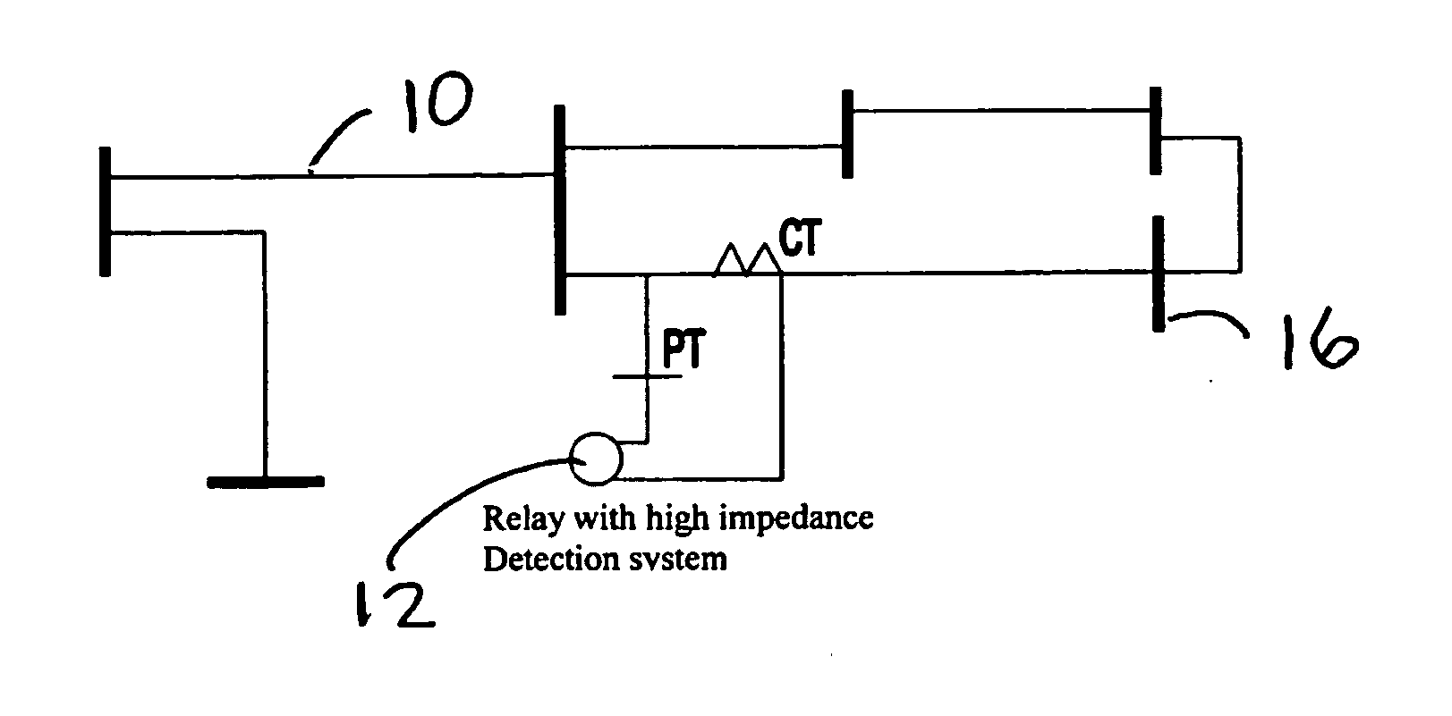
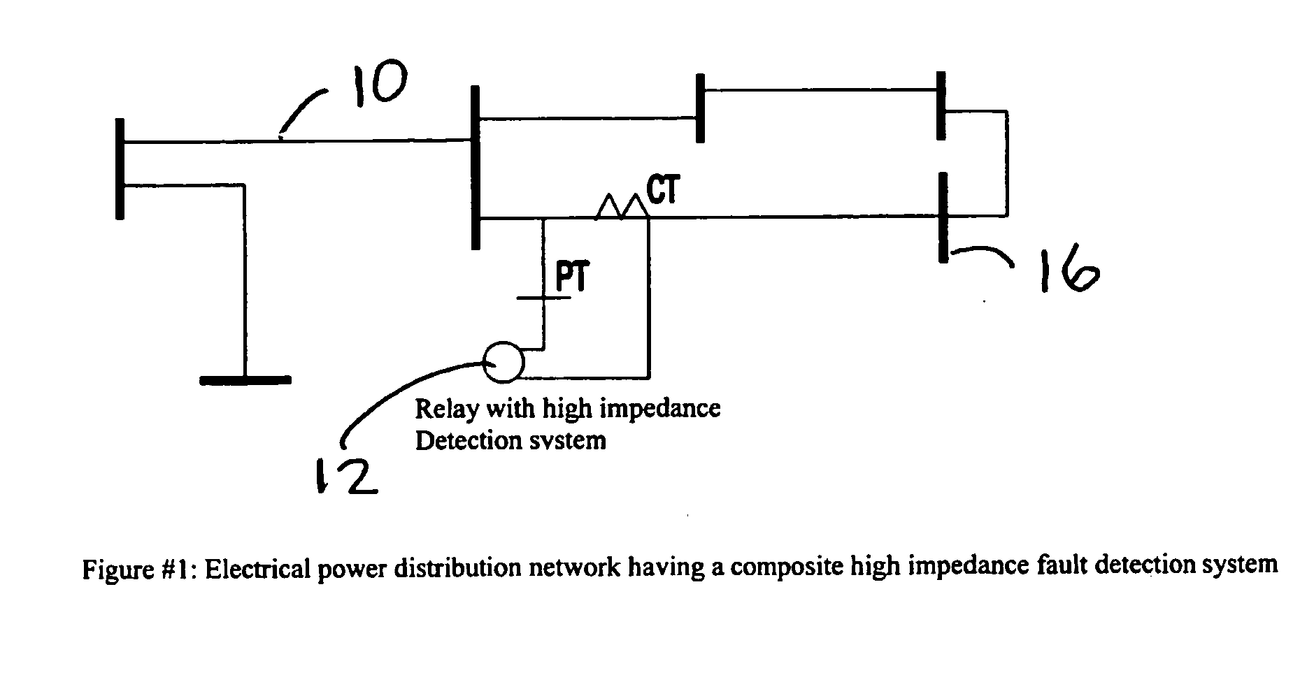
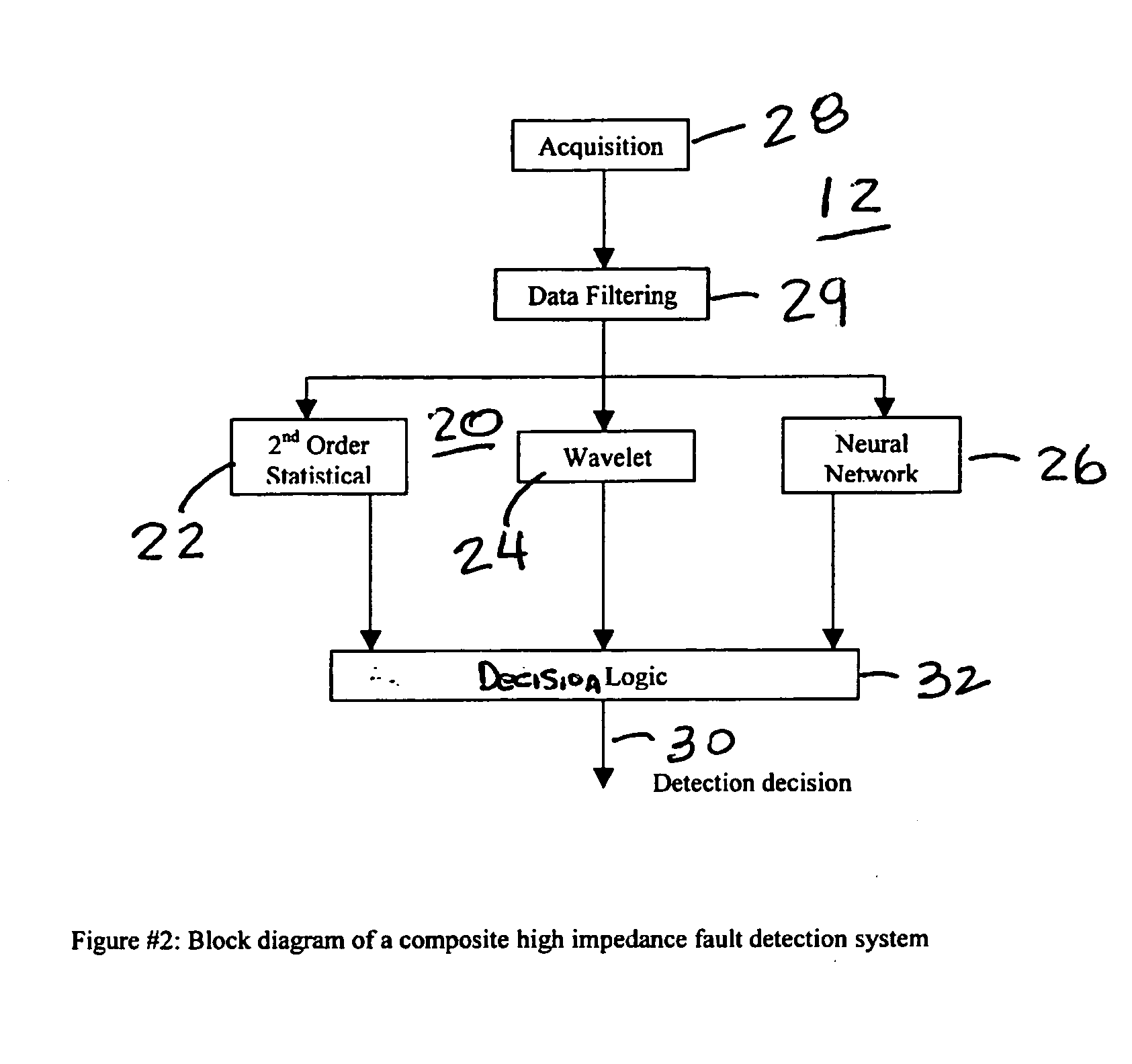
[0046] The present invention considers high impedance faults in a multi-resolution framework. The present invention relates to a new approach to high impedance fault detection that includes a multi-scheme high impedance fault detection scheme employing a plurality of individual fault detection systems each having their own algorithm application that use various features of phase and / or ground currents to individually detect a high impedance fault. Suitable features of the currents include their wavelength signatures, their fourth order moment, their sample values as seen by a neural net, and the like. FIG. 1 shows a schematic diagram of an electrical power distribution system having an electrical power distribution line 10 and a composite high impedance detection system 12. The solid vertical bars in FIG. 1 are bus bars 16 and represent the interconnection of multiple distribution lines. The composite high impedance detection system 12 includes a plurality of individual high impeda...


PUM


Abstract

An apparatus, system, and method for detecting high impedance faults in electrical power lines using a composite high impedance fault detection system having a voter logic that samples the logical outputs from a plurality of independent high impedance detection systems and determines a high impedance fault if any two of the plurality of independent high impedance detection systems indicates a high impedance fault. Preferably, the plurality of high impedance detection systems include a wavelet based high impedance fault detection system having a first logical output, a higher order statistics based high impedance fault detection system having a second logical output, and a neural net based high impedance fault detection system having a third logical output. Preferably, each of the plurality of high impedance fault detection systems includes an independent high impedance fault detection application that independently detects a high impedance fault on the electrical power line.

Description

1. FIELD OF THE INVENTION [0001] The present invention relates in general to fault detection in electrical power systems, and particularly, to high impedance fault detection in electrical power distribution lines. 2. DESCRIPTION OF THE PRIOR ART [0002] High impedance faults are characterized by a high impedance at the point of fault. Accordingly, a high impedance fault typically produces a small fault current level. High impedance faults can, therefore, be generally defined as those faults that do not draw sufficient fault current to be recognized and cleared by conventional overcurrent devices, such as protective relays. [0003] High impedance faults result when an energized primary conductor comes in contact with a quasi-insulating object, such as a tree, a structure or equipment, a pole crossarm, or falls to the ground. Typically, a high impedance fault exhibits arcing and flashing at the point of contact. The significance of these hard to detect faults is that they represent a se...

Claims


Application Information

Patent Timeline
Patent Type & Authority Applications(United States)
IPC IPC(8): G01R31/50H02H1/00H02H3/05
CPCG01R31/025H02H3/05H02H1/0092H02H1/0015G01R31/52G01R31/50
Inventor KUNSMAN, STEVEN A.JOUNY, ISMAIL I.KAPRIELIAN, STEPHEN
Owner ABB INC
Why Eureka
Try Eureka