Drive device for suspended members

a technology for driving devices and suspended members, which is applied in the direction of power supplies, door/window fittings, constructions, etc., can solve problems such as difficulty in handling, and achieve the effect of improving appearance and being easy to handl

Inactive Publication Date: 2005-08-11
ASMO CO LTD
View PDF9 Cites 49 Cited by
  • Summary
  • Abstract
  • Description
  • Claims
  • Application Information

AI Technical Summary

Benefits of technology

[0004] Accordingly, it is an objective of the present invention to provide a suspended member drive device

Problems solved by technology

However, the prior art drive device needs a line for supplying pow

Method used


Image

  • Drive device for suspended members
  • Drive device for suspended members
  • Drive device for suspended members

Examples


first embodiment

[0019] an electric curtain device, or a suspended member drive device, according to the present invention will hereafter be described with reference to FIGS. 1 to 7.

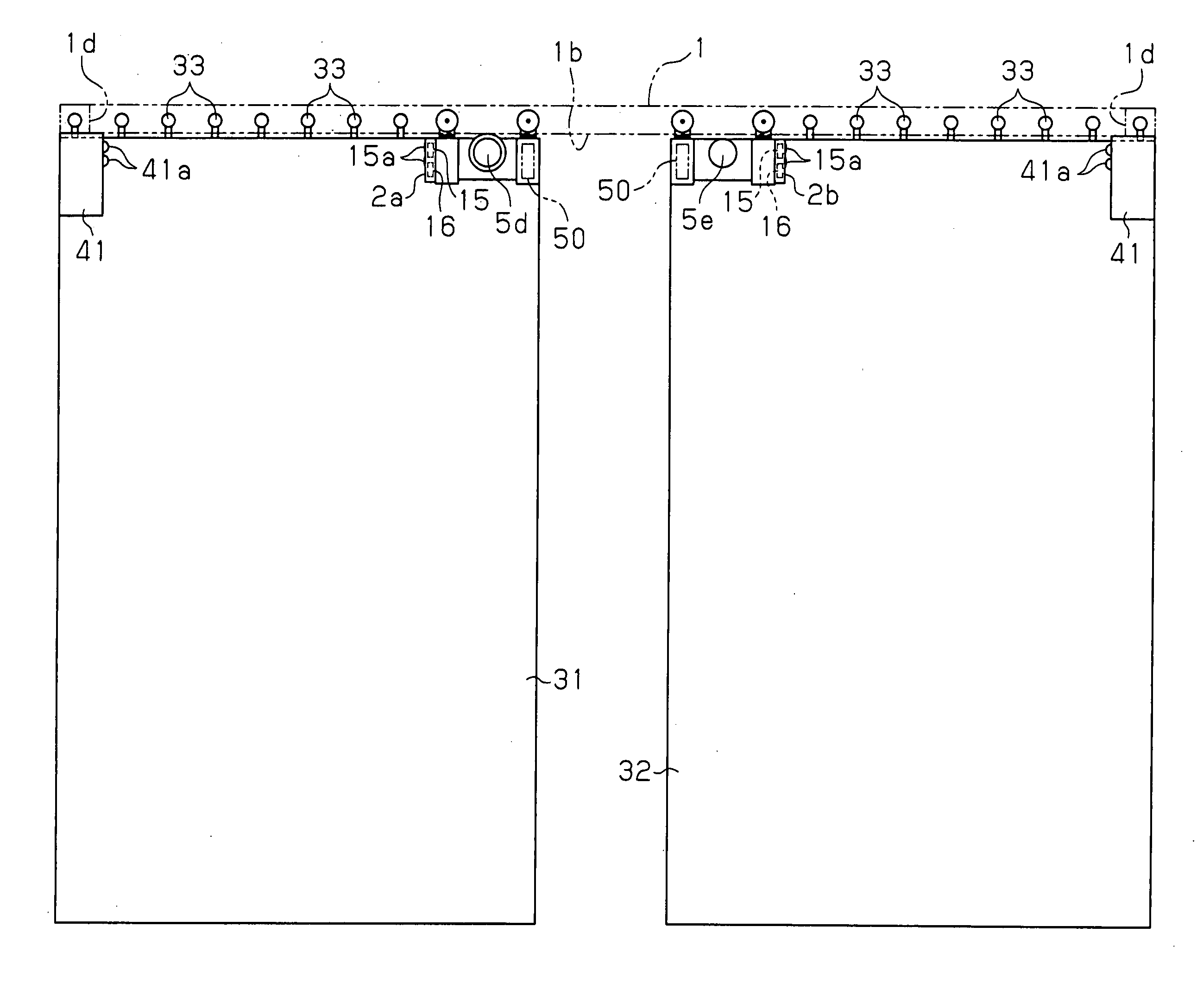
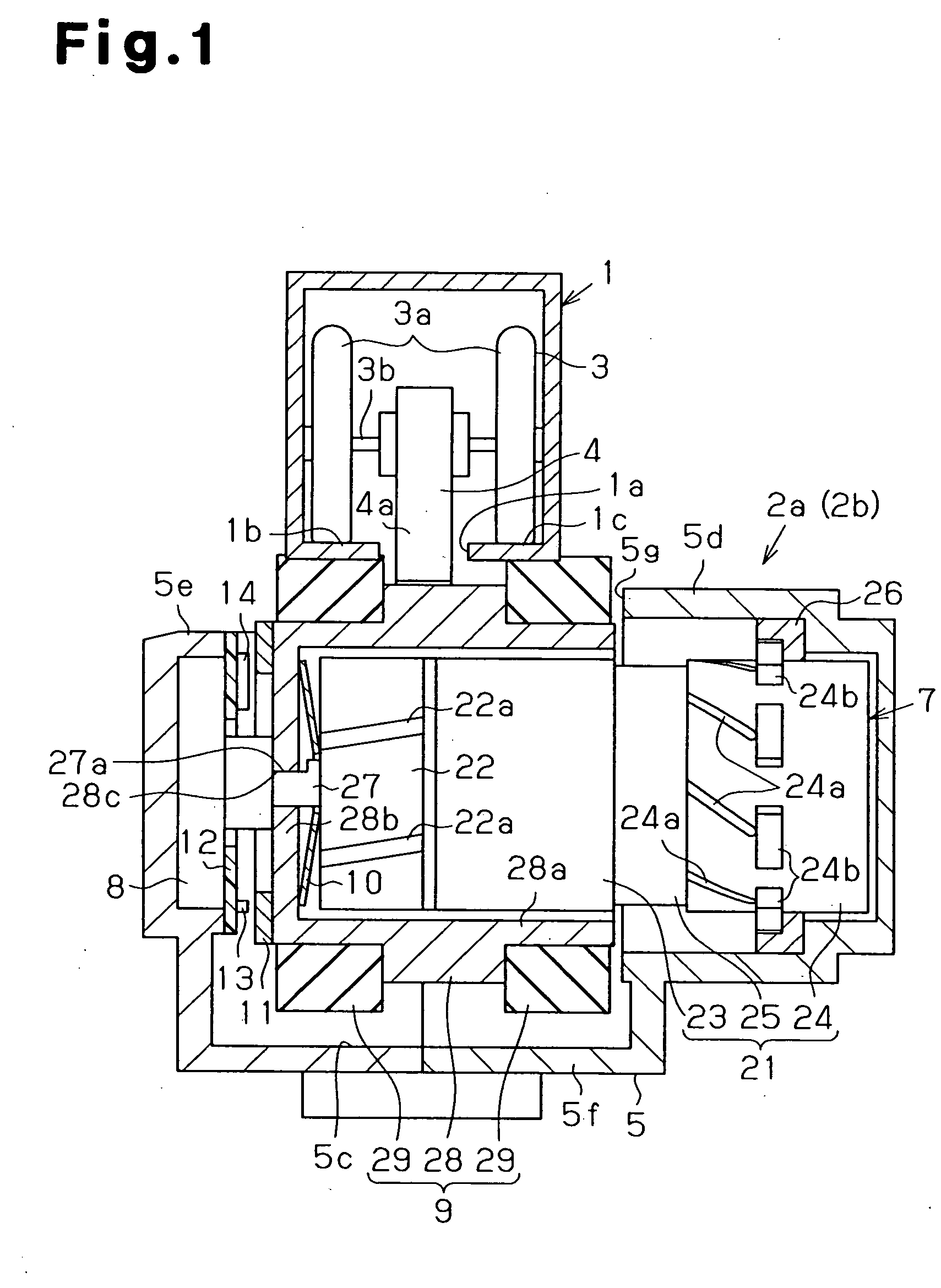
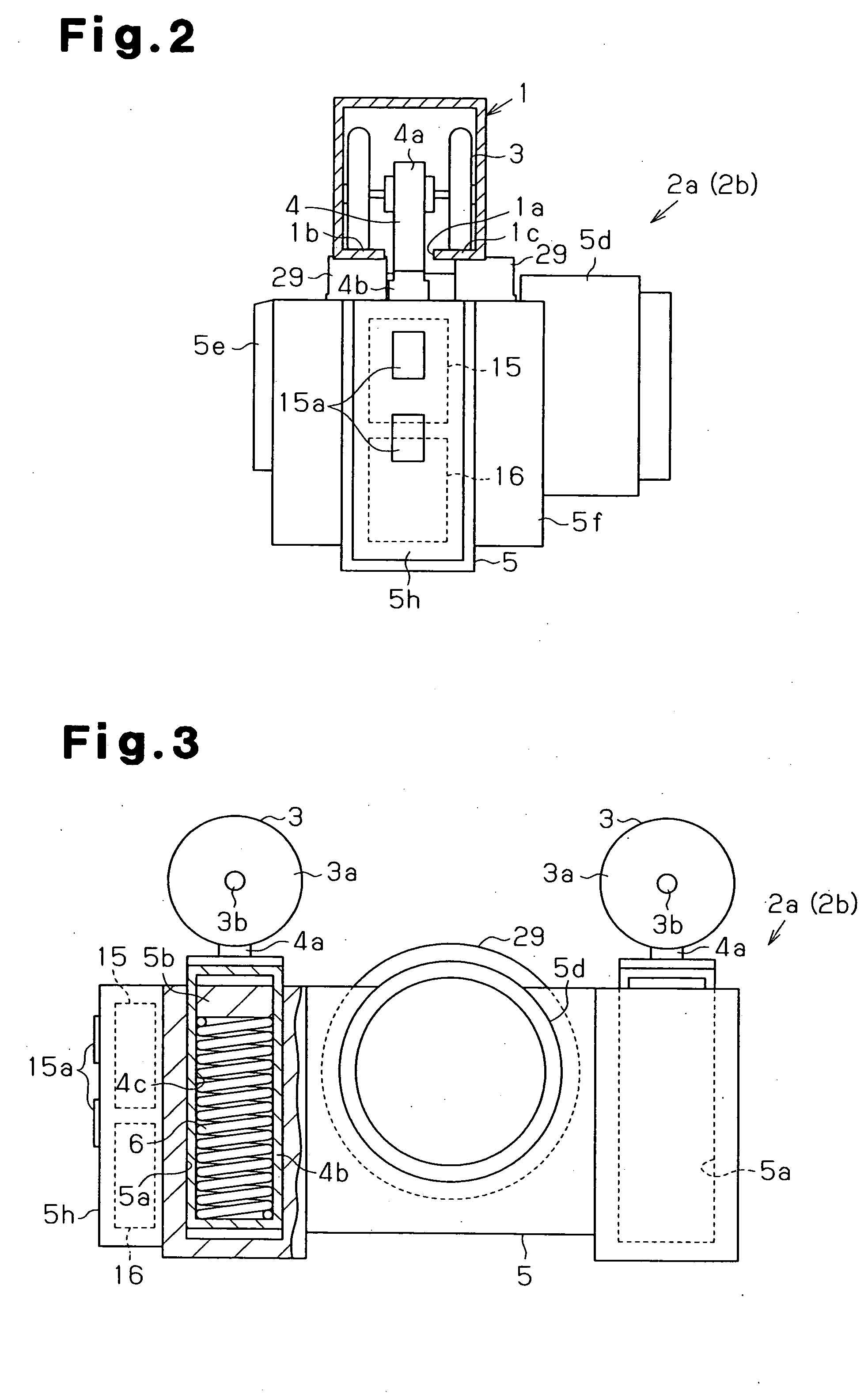
[0020] Referring to FIGS. 1 to 4, a curtain rail 1 is shaped substantially like a hollow square pole. A slit la is defined in a lower side of the curtain rail 1 and extends along the longitudinal direction of the curtain rail 1. A pair of opposing support portions 1b, 1c are formed by a pair of lower wall sections of the curtain rail 1. The slit la is located between the support portions 1b, 1c. As shown in FIG. 5, a pair of running members 2a, 2b is provided in the curtain rail 1 in a manner movable along the curtain rail 1.

[0021] Each of the running members 2a, 2b includes a pair of runners 3, a pair of connecting members 4, a casing 5, a pair of compression springs 6, a supersonic motor 7 serving as an actuator, a bearing 8, a rotary member 9, a disc spring 10, a sensor magnet 11, a base plate 12, a Hall element 13, ...

second embodiment

[0063] The second embodiment has the following advantages.

[0064] If the running member 102 reaches the right end 101g or the left end 101h of the curtain rail 101, the end reaching signal is generated by the contact between the end 101g, 101h and the corresponding switch 115. When the initial setting means initially moves the running member 102 from the right end 101g to the left end 101h of the curtain rail 101, the rail length data is set for the controller 114, or the position acquiring means, in correspondence with the end reaching signals. Setting of the rail length data is thus relatively easy and highly accurate. Accordingly, the position acquiring means is allowed to acquire the position of the running member 102 on the curtain rail 101 with improved accuracy. This also enhances the accuracy of operation of the control means based on the acquired position of the running member 102.

[0065] When the running member 102 is moved from the stopped state toward the right end 101g o...


PUM


Abstract

An electric curtain device of the present invention includes a pair of running members and a pair of chargers arranged at opposed ends of a curtain rail. The running members are movable along the curtain rail and support a pair of curtains, respectively, in a suspended state. Each of the running members includes a supersonic motor and is moved along the curtain rail when actuated by a supersonic motor. Further, each running member has a battery and a driver. The electric curtain device is relatively easy to handle. Further, the appearance of the device is improved without requiring machining of the curtain rail.

Description

BACKGROUND OF THE INVENTION [0001] The present invention relates to drive devices for moving a suspended member, such as a curtain along a rail. [0002] Japanese Laid-Open Patent Publication No. 2001-37622 describes a drive device for a suspended member. A running member is movable along a curtain rail and supports a curtain, which is a suspended member, in a suspended state. More specifically, the running member is provided with an actuator such as a motor and is moved along the rail by drive force of the actuator. The drive device is operated through, for example, manipulation of a remote controller switch, such that the curtain is selectively extended or folded. [0003] However, the prior art drive device needs a line for supplying power to the actuator, or a power cable, which is difficult to handle. Also, the curtain rail must be machined in a particular manner for preventing exposure of the cable to the exterior, in order to improve the appearance of the curtain rail. Alternativ...

Claims


Application Information

Patent Timeline
IPC IPC(8): A47H5/02E05F15/14E05F15/60
CPCA47H5/0325E05Y2201/434E05Y2400/614E05F15/632E05Y2400/66E05Y2600/46E05F15/60E05Y2400/656E05F15/641
Inventor KOMODA, MASAHIKO
Owner ASMO CO LTD
Why Eureka
Try Eureka