Fuel vapor pipe structure of fuel tank

a technology of fuel vapor pipe and fuel tank, which is applied in the direction of liquid fuel feeders, functional valve types, machines/engines, etc., can solve the problems of poor operation and handling performance, inability to connect valves, and high fabrication costs, so as to achieve the effect of alleviating the need for resin tubes

Inactive Publication Date: 2005-08-11
PIOLAX CO LTD
View PDF13 Cites 33 Cited by
  • Summary
  • Abstract
  • Description
  • Claims
  • Application Information

AI Technical Summary

Benefits of technology

[0017] According to the second aspect of the invention, when the resin tubes are connected to the respective connection tube portions to pipe, the resin tubes are bent substantially in point symmetry centering on the pipe joint and therefore, end portions of the respective resin tubes can be inserted to connect to the connection tube portions of the pipe joint substantially from coaxial directions and therefore, a forcible bent portion is not produced in the resin tube and stresses applied to the pipe joint and the resin tube can be alleviated.
[0018] According to the fuel vapor pipe structure, an allowance is provided to the length of the resin tube, dispersions in dimensions of the respective parts are made to be able to be absorbed, a direction of bending the resin tube when piped is rectified and it can be prevented that the resin tube interferes with other member, or is stored with a liquefied fuel and stresses which are not anticipated in designing can be prevented from being applied to the cut valve or the pipe joint.

Problems solved by technology

According to the pipe structure of the background art using a tube made of rubber, after outwardly fitting the tube made of rubber to the connection tube portion, the tube needs to be connected and fixed by the hose strap and therefore, there poses a problem that operability and handling performance are poor and fabrication cost is also high.
However, although in such a pipe structure, strict dimensional accuracy is requested for the resin tube, actually, the dimension is liable to be dispersed by various dispersions, for example, a dispersion by cutting in molding the resin tube, a dispersion by a press-fitting margin in press-fitting the resin tube to connection tubes of respective valve members, a dispersion by contracting the resin tube by a temperature change after being attached to the fuel tank or evaporation of moisture in the resin tube, a dispersion by swelling the resin tube by adhering fuel vapor and so on.
Further, the resin tube is devoid of flexibility and difficult to be elongated in comparison with the tube made of rubber and therefore, when the resin tube is going to attach to inside of the fuel tank in a state of being previously connected with the cut valve or the check valve, by dispersion in an interval between the cut valve and check valve to be connected, there is brought about a drawback that the valves cannot be connected since a length of the resin tube becomes deficient, even when the valves can be connected, the resin tube is liable to be drawn out, and when conversely, the length becomes excessively long, the resin tube is brought into contact with other part to interfere therewith, or a middle portion of the resin tube is hung down and fuel is liable to be stored at the middle of the tube.

Method used


Image

  • Fuel vapor pipe structure of fuel tank
  • Fuel vapor pipe structure of fuel tank
  • Fuel vapor pipe structure of fuel tank

Examples


Embodiment Construction

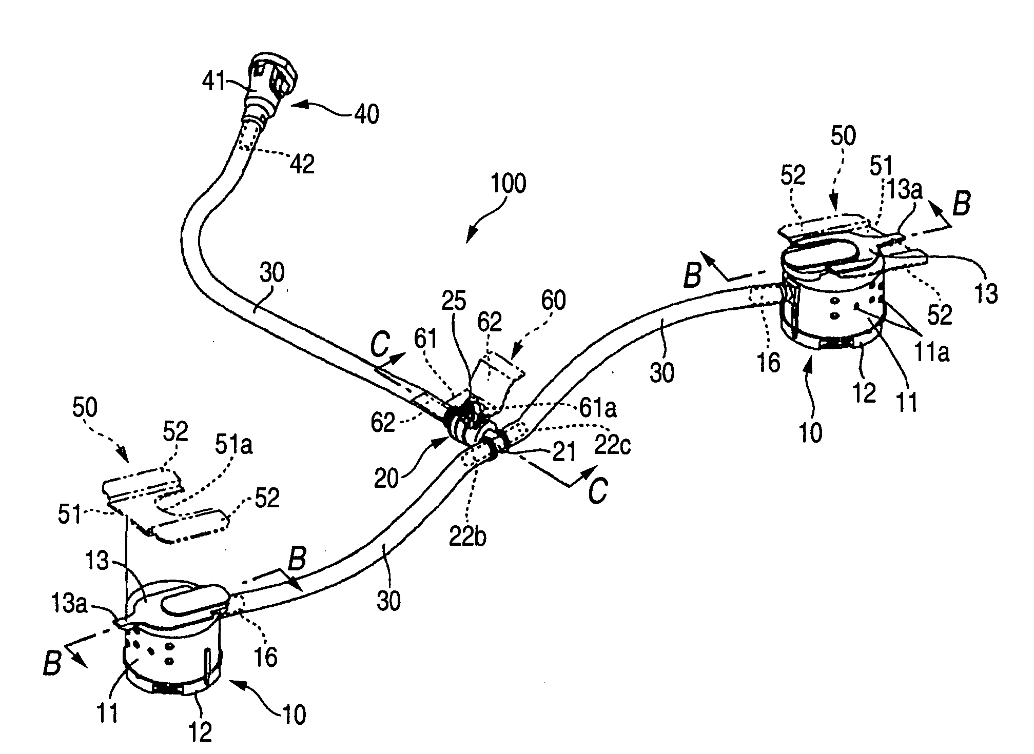
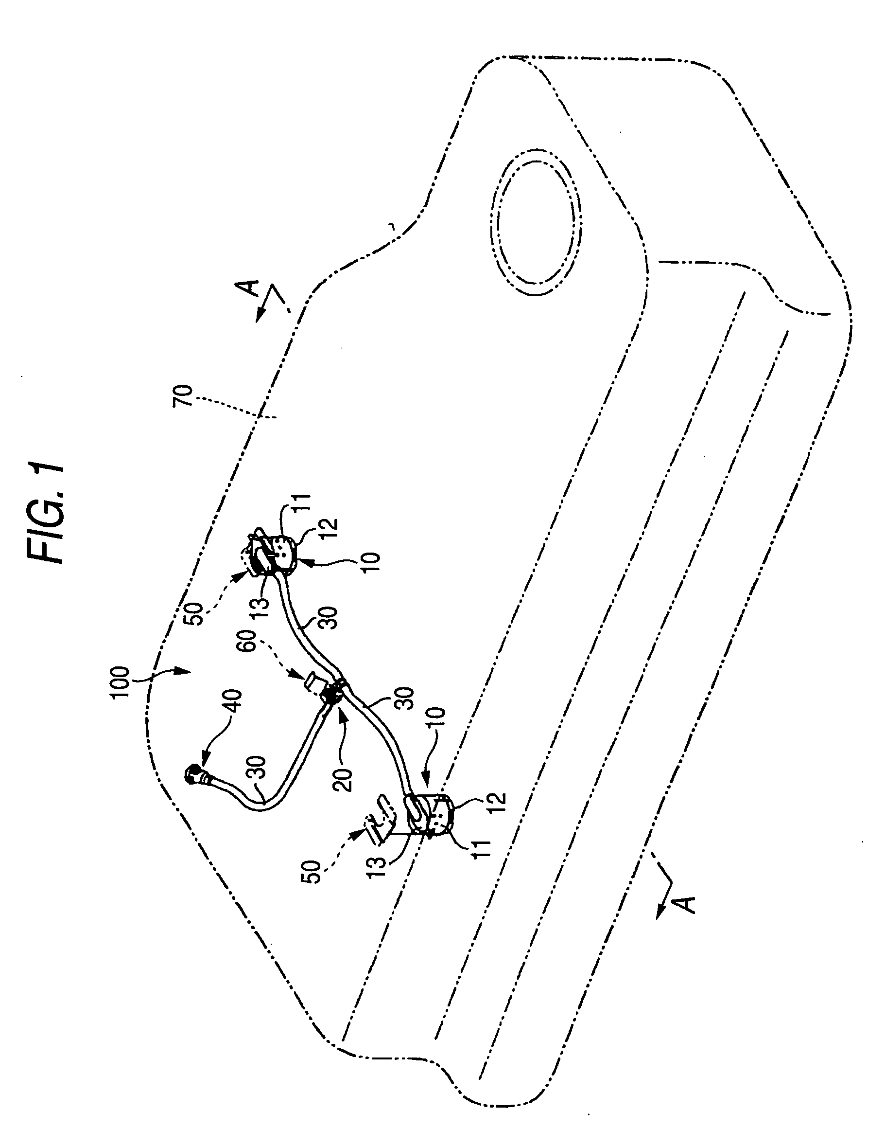
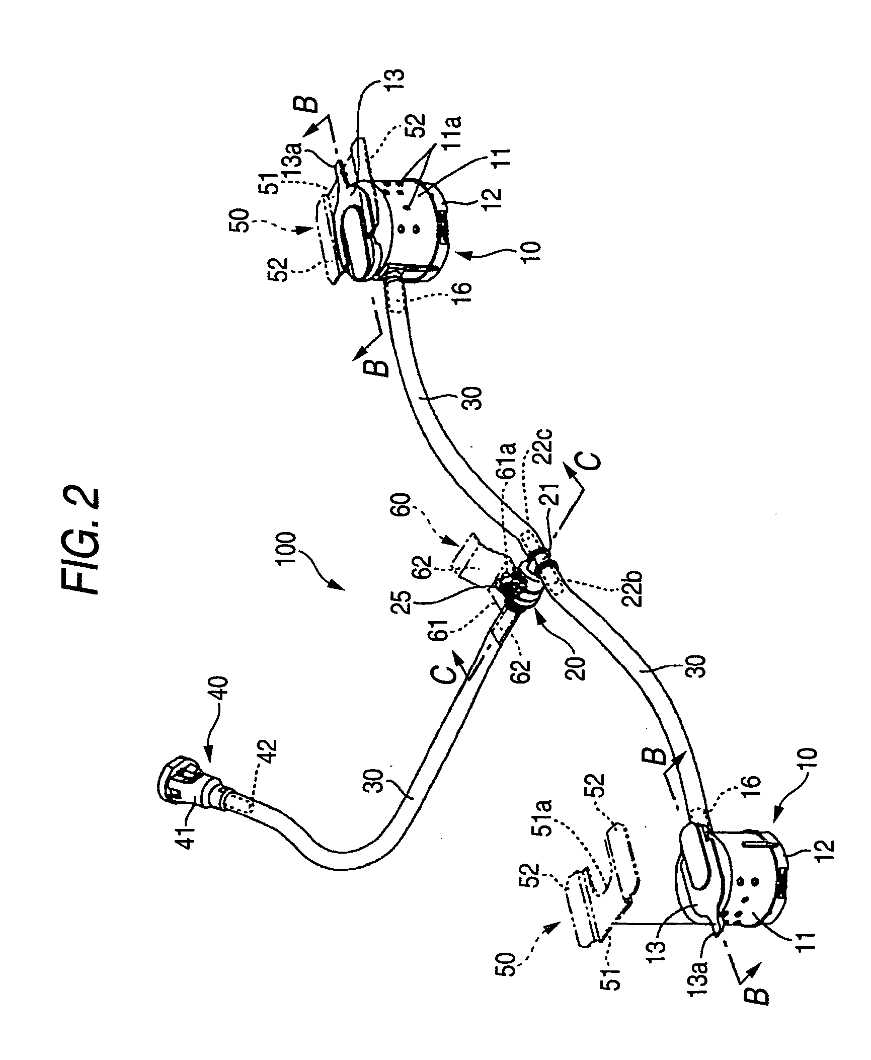
[0028] An embodiment of the invention will be explained in reference to the drawings as follows. FIGS. 1 through 6 show an embodiment of a fuel pipe structure of a fuel tank. FIG. 1 is a perspective view showing a total of a fuel vapor pipe structure of the fuel tank, FIG. 2 is a perspective view enlarging the fuel vapor pipe structure of the fuel tank, FIG. 3 is a plane view of the fuel vapor pipe structure of the fuel tank, FIG. 4 is a side view of the fuel vapor structure of the fuel tank taken along an arrow mark line of A-A of FIG. 1, FIG. 5 is a sectional view of a cut valve which is a constituent member of the fuel vapor pipe structure of the fuel tank taken along an arrow mark line of B-B of FIG. 2, and FIG. 6 is a sectional view of a pipe joint which is a constituent member of the fuel vapor pipe structure of the fuel tank taken along an arrow mark line of C-C of FIG. 2.

[0029] As shown by FIG. 1, a fuel vapor pipe structure 100 of the fuel tank is mainly constituted by a p...


PUM


Abstract

In a fuel vapor pipe structure including a plurality of cut valves for passing or cutting a fuel vapor at inside of a fuel tank, a pipe joint connected to the cut valves for communicating the fuel vapor to a canister, and a resin tube for connecting the cut valve and the pipe joint, the resin tube is bent to pipe by making a length of the resin tube longer than a length of connecting connection tube portions of the cut valve and connection tube portions of the pipe joint and arranging the connection tube portion of the cut valve to shift from a straight line of connecting a center of the cut valve and a center of the pipe joint by a predetermined angle in a horizontal direction.

Description

BACKGROUND OF THE INVENTION [0001] 1. Field of the Invention [0002] The present invention relates to a fuel vapor pipe structure of a fuel tank of an automobile, particularly relates to a fuel vapor pipe structure using a resin tube. [0003] 2. Description of the Related Art [0004] A fuel tank of an automobile is attached with a cut valve for escaping fuel vapor at inside of a fuel tank to outside and preventing fuel rocked by turning or inclining the automobile from leaking to outside of the fuel tank. [0005] Generally, the cut valve is connected to a check valve for making fuel vapor flow to outside when a fuel vapor pressure is higher than a predetermined value and connected to a canister arranged outside of the fuel tank from the check valve. [0006] In connecting the cut valve and check valve, normally, the cut valve and the check valve are connected by outwardly fitting end portions of a tube made of rubber to respective connection tube portions thereof and fastening an outer pe...

Claims


Application Information

Patent Timeline
Patent Type & Authority Applications(United States)
IPC IPC(8): B60K15/01B60K15/035F02M25/08F02M37/00F16K24/04
CPCB60K15/035F16K24/04B60K2015/03523B60K15/03519Y10T137/0874Y10T137/3099
Inventor OHSHIRO, ATSUSHINISHINO, RYO
Owner PIOLAX CO LTD
Why Eureka
Try Eureka