Plasma processing apparatus

a processing apparatus and plasma technology, applied in the direction of vacuum evaporation coating, manufacturing tools, electric/magnetic/electromagnetic heating, etc., can solve the problems of uneven electromagnetic field in the interior of the processing container, and the inability to produce plasma uniformly

Inactive Publication Date: 2005-08-11
TOKYO ELECTRON LTD
View PDF5 Cites 16 Cited by
  • Summary
  • Abstract
  • Description
  • Claims
  • Application Information

AI Technical Summary

Benefits of technology

[0022] The fourth feature of the present invention resides in that the traveling-wave generator has a multiphase high-frequency wave supplier for supplying several positions apart from each other in the circumferential direction of the annular waveguide with high-frequency waves whose phases are shifted from each other in the circumferential direction, whereby the supply of the high-frequency waves whose phases are shifted from each other in the circumferential direction of the annular waveguide allows the traveling wave to be generated in the annular waveguide.

Problems solved by technology

Thus, due to the positional relationship between node and antinode in the antenna, a problem arises in that the interior of the processing container has an electromagnetic field of uneven intensity.
Additionally, if the position of each node of the standing wave is deviated from the slot of the antenna, the uniformity of electromagnetic field cannot be maintained in the processing container, causing a problem of impossibility to produce the plasma uniformly, hitherto.

Method used


Image

  • Plasma processing apparatus
  • Plasma processing apparatus
  • Plasma processing apparatus

Examples


first embodiment

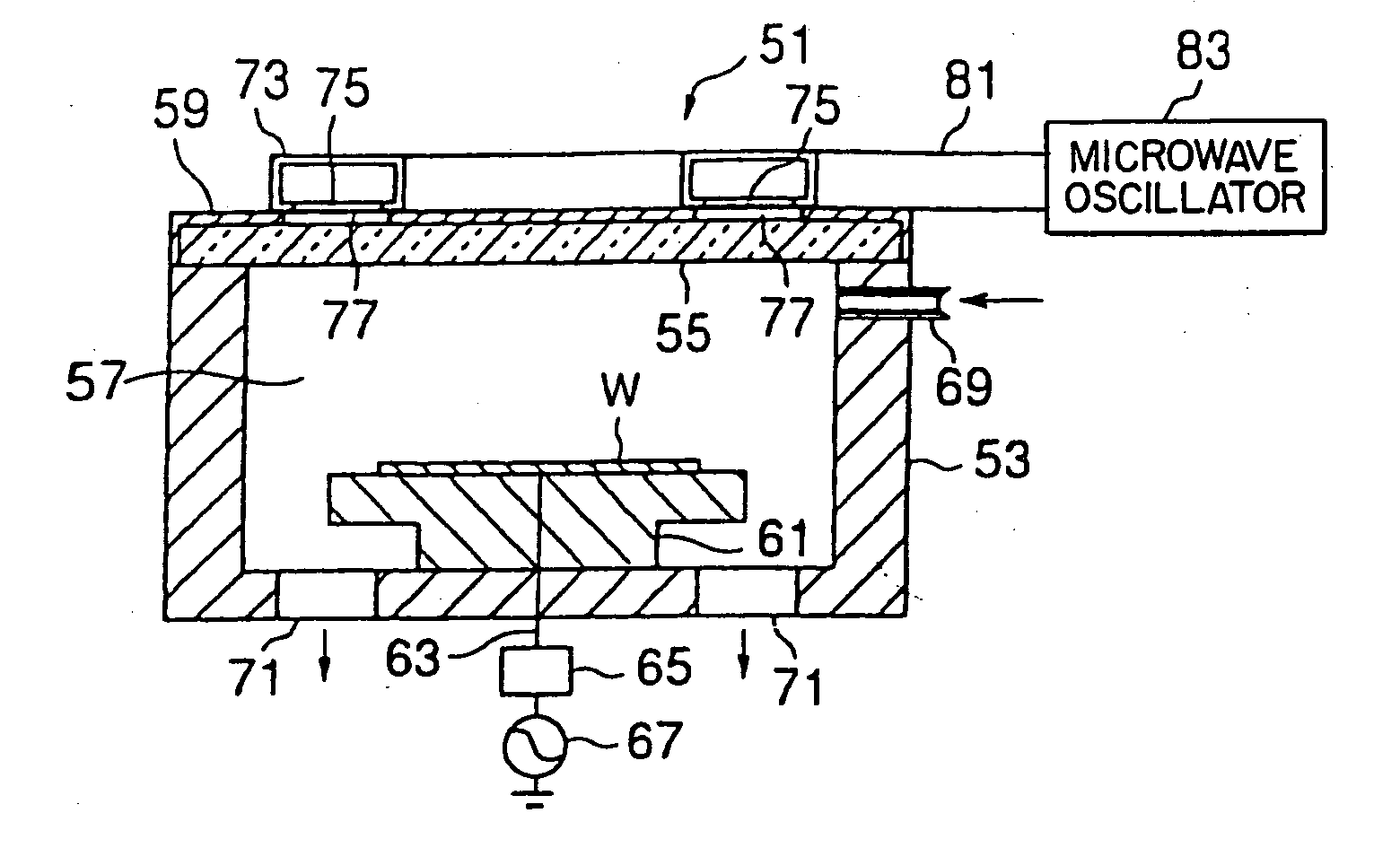
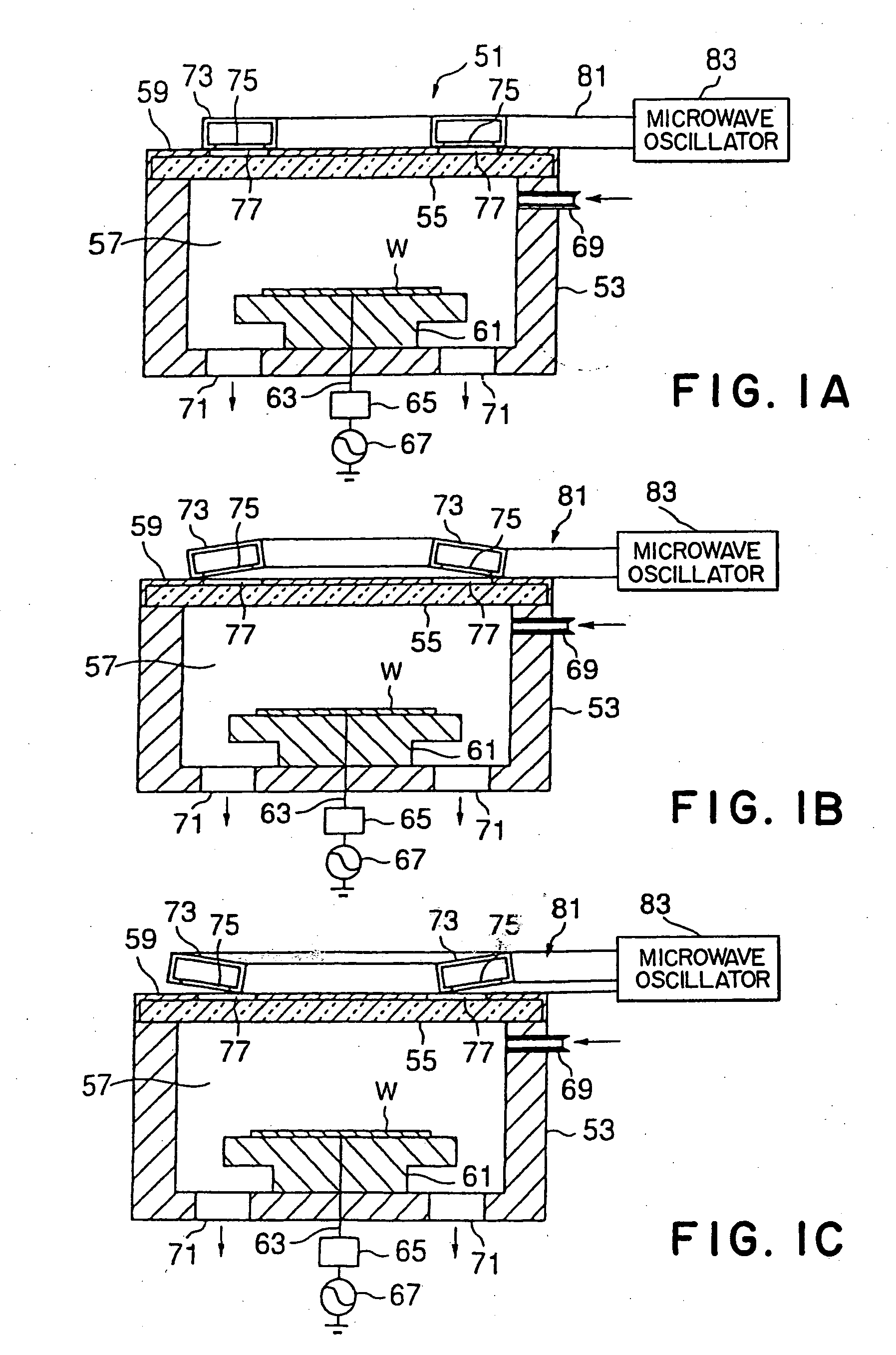
[0063]FIGS. 1A, 1B, 1C and 2 are structural views showing the plasma processing apparatus of the In FIG. 1A, this plasma etching apparatus 51 has a processing container 53 whose sidewall and bottom are made of conductive material, such as aluminum, and which is shaped to be a cylinder with bottom, as a whole. The ceiling part of the container 53 is opened, whereas it is sealed by a sealing plate 55 having a thickness to endure a vacuum pressure through a sealant, such as O-ring, in an air-tight manner. This sealing plate 55 is made from dielectric material exhibiting heat-resistance, microwave permeability and small dielectric loss, for example, silica glass, alumina, ceramics of aluminum nitride or the like. Owing to the provision of the sealing plate 55, there is defined a processing space 17 in the processing container 53. Fitted on the sealing plate 55 is a cover member 59 in the form of a circular lid of conductive material, which is fixed on the processing container 53.

[0064]...

second embodiment

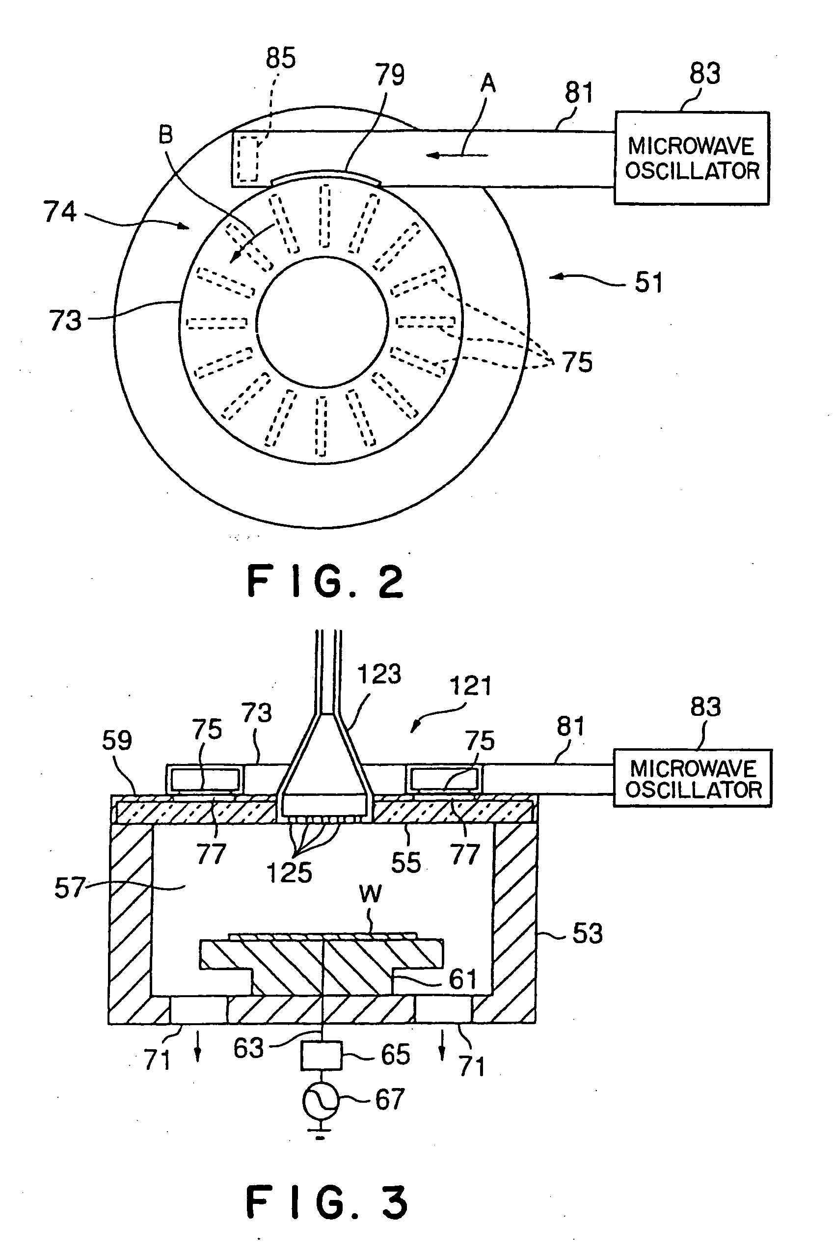
[0071]FIG. 3 is a view showing a plasma processing apparatus 121 in accordance with the present invention. This plasma processing apparatus 121 is similar to the plasma processing apparatus 51 besides a gas supply tube 123 arranged at the center of the sealing plate 55 surrounded by the annular antenna 73. This gas supply tube has a lower part funnel-shaped so as to gradually increase its diameter as approaching the lowermost end provided with a number of nozzles 125. In this way, since the antenna 73 supplying the processing container 53 with the microwave is in the form of a circular loop, the gas supply tube 123 can be provided at the central opening of the antenna 53. Accordingly, it is possible to supply the wafer W with reactive gas etc. uniformly, thereby preventing the uneven processing due to unequal gas supply.

third embodiment

[0072]FIG. 4 is a view showing a plasma processing apparatus 131 in accordance with the present invention. This plasma processing apparatus 131 is similar to the plasma processing apparatus 51 besides an opposing electrode 133 arranged at the center of the sealing plate 55 surrounded by the annular antenna 73 so as to oppose the mounting table 61. The opposing electrode 133 is grounded for earthing. With this arrangement, it is possible to form a strong and uniform electromagnetic field between the mounting table 61 and the opposing electrode 133, whereby ions can be extracted from the plasma effectively, accomplishing an uniform processing.

[0073]FIG. 5 is a view showing a plasma processing apparatus 141 in accordance with the fourth embodiment of the present invention. This plasma processing apparatus 141 is similar to the plasma processing apparatus 131 of the third embodiment in FIG. 4 besides a high-frequency source 143 in place of the earth for the opposing electrode 133. In th...


PUM

PropertyMeasurementUnit
frequencyaaaaaaaaaa
frequencyaaaaaaaaaa
diameteraaaaaaaaaa

Abstract

A plasma processing apparatus includes a processing container 53, a mounting table 61 arranged in the processing container 53 to support a wafer W, a sealing plate 55 opposed to the wafer W supported by the mounting table 61, an annular antenna 73 arranged on the sealing plate 55 and consisting of an annular waveguide to introduce a microwave into the processing container 53 through the sealing plate 55, the annular antenna 73 being arranged so that a plane containing an annular waveguide path defined by the annular waveguide is generally parallel with the sealing plate 55, a directional coupler 79 arranged on the periphery of the annular antenna 73, a propagation waveguide 81 connected to the directional coupler 79 and a microwave oscillator 83 connected to the propagation waveguide 81. Accordingly, it is possible to form an uniform microwave in the antenna, so that an uniform plasma can be produced in the processing container.

Description

BACKGROUND OF THE INVENTION [0001] 1. Technical Field of the Invention [0002] The present invention relates to a plasma processing apparatus utilizing a high-frequency wave. [0003] 2. Description of the Related Art [0004] Conventionally, there is known a plasma processing apparatus which includes an antenna consisting of an annular waveguide arranged on the upper face of a processing container to supply its interior with a microwave, as shown in FIG. 17 (Japanese Patent Publication kokai No. 11-121196). [0005] This plasma processing apparatus 11 has a processing container 13 on which an antenna 15 is mounted. The antenna 15 is formed by an annularly-curled waveguide having its end closed and has slots 17 . . . formed on the side of the processing container15. The other end of the antenna 15 is connected to a microwave oscillator 19. [0006] In the plasma processing apparatus 11, the microwave from the microwave oscillator 19 is reflected on an end 21 of the antenna 15 to form a stand...

Claims


Application Information

Patent Timeline
Patent Type & Authority Applications(United States)
IPC IPC(8): H01J37/32
CPCH01J37/32192H01J37/32293H01J37/32229
Inventor ISHII, NOBUOSHINOHARA, KIBATSU
Owner TOKYO ELECTRON LTD
Why Eureka
Try Eureka