Data collection system having a data collector

a data collection and data technology, applied in the direction of vehicle position/course/altitude control, process and machine control, instruments, etc., can solve the problems of data center cooling, temperature exceeding a predetermined temperature range, and computer systems in the data center may only utilize around 30-50% of the maximum cooling capacity

Active Publication Date: 2005-08-11
HEWLETT-PACKARD ENTERPRISE DEV LP
View PDF6 Cites 43 Cited by
  • Summary
  • Abstract
  • Description
  • Claims
  • Application Information

AI Technical Summary

Benefits of technology

[0009] According to an embodiment, the present invention pertains to a system for collecting data in a room. The system includes a plurality of sensor devices positioned at various locations in the room. The sensor devices include a sensor configured to detect at least one condition and a controller configured to control the sensor. The system also includes

Problems solved by technology

As such, the cooling of data centers presents problems in addition to those faced with the cooling of the racks.
However, the computer systems in the data center may only utilize around 30-50% of the maximum cooling capacity.
In this respect, conventional cooling systems often attempt to cool components that may not be operating at a level which may cause their temperatures to exceed a predetermined temperature range.
Consequently, conventional cooling systems often incur greater amounts of operating expenses than may be necessary to sufficiently cool the heat generating components contained in the racks of data centers.
Another problem associated with the cooling of data centers involves the expense and difficulty in measuring the environmental conditions, e.g., temperature, humidity, air flow, etc., within and around the racks.
Although it has been found that the use of temperature sensors, e.g., thermocouples, located at various locations throughout the data center has been a relatively accurate manner of detecting temperatures, this practice has also b

Method used


Image

  • Data collection system having a data collector
  • Data collection system having a data collector
  • Data collection system having a data collector

Examples


Embodiment Construction

[0018] For simplicity and illustrative purposes, the present invention is described by referring mainly to an exemplary embodiment thereof. In the following description, numerous specific details are set forth in order to provide a thorough understanding of the present invention. It will be apparent however, to one of ordinary skill in the art, that the present invention may be practiced without limitation to these specific details. In other instances, well known methods and structures have not been described in detail so as not to unnecessarily obscure the present invention.

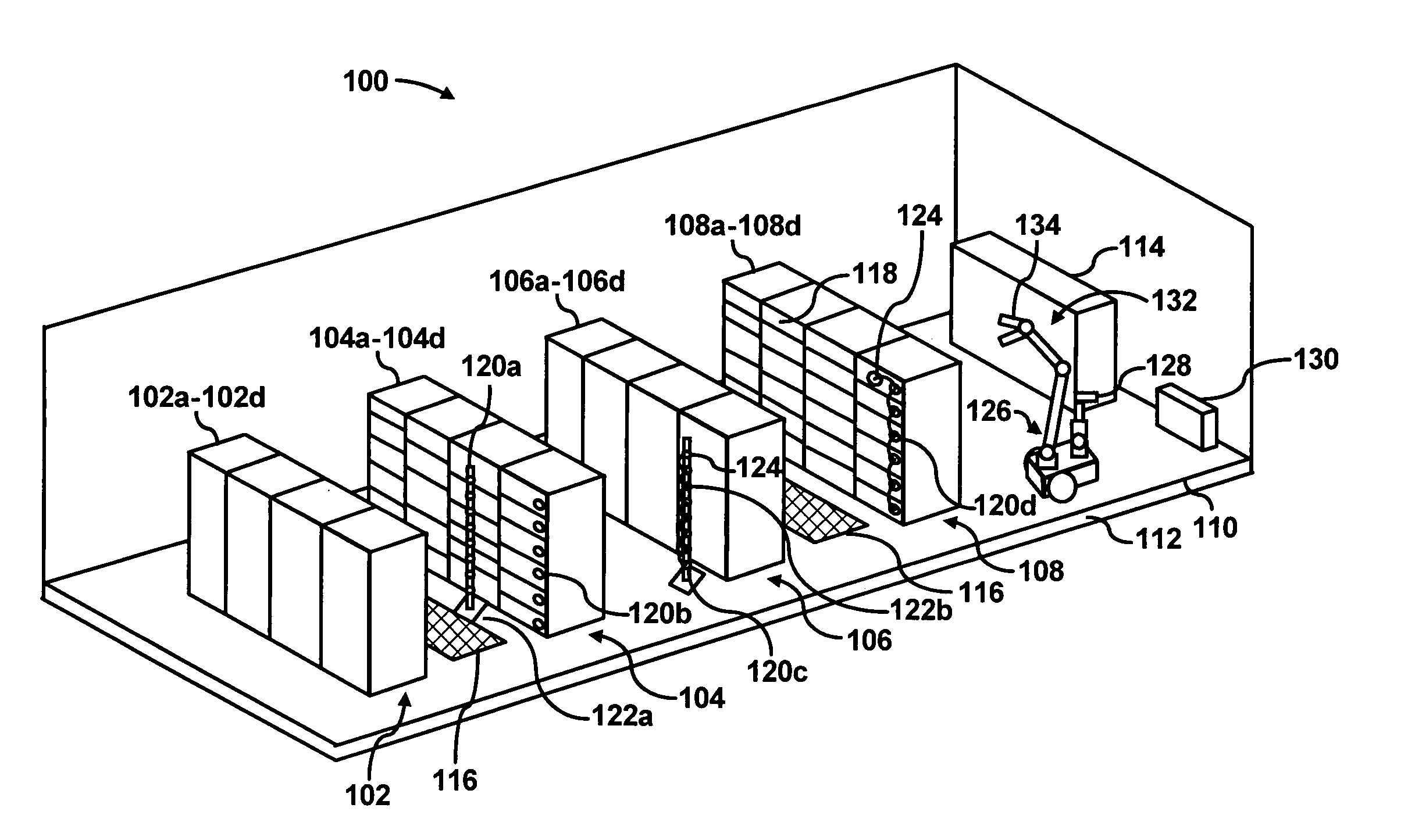
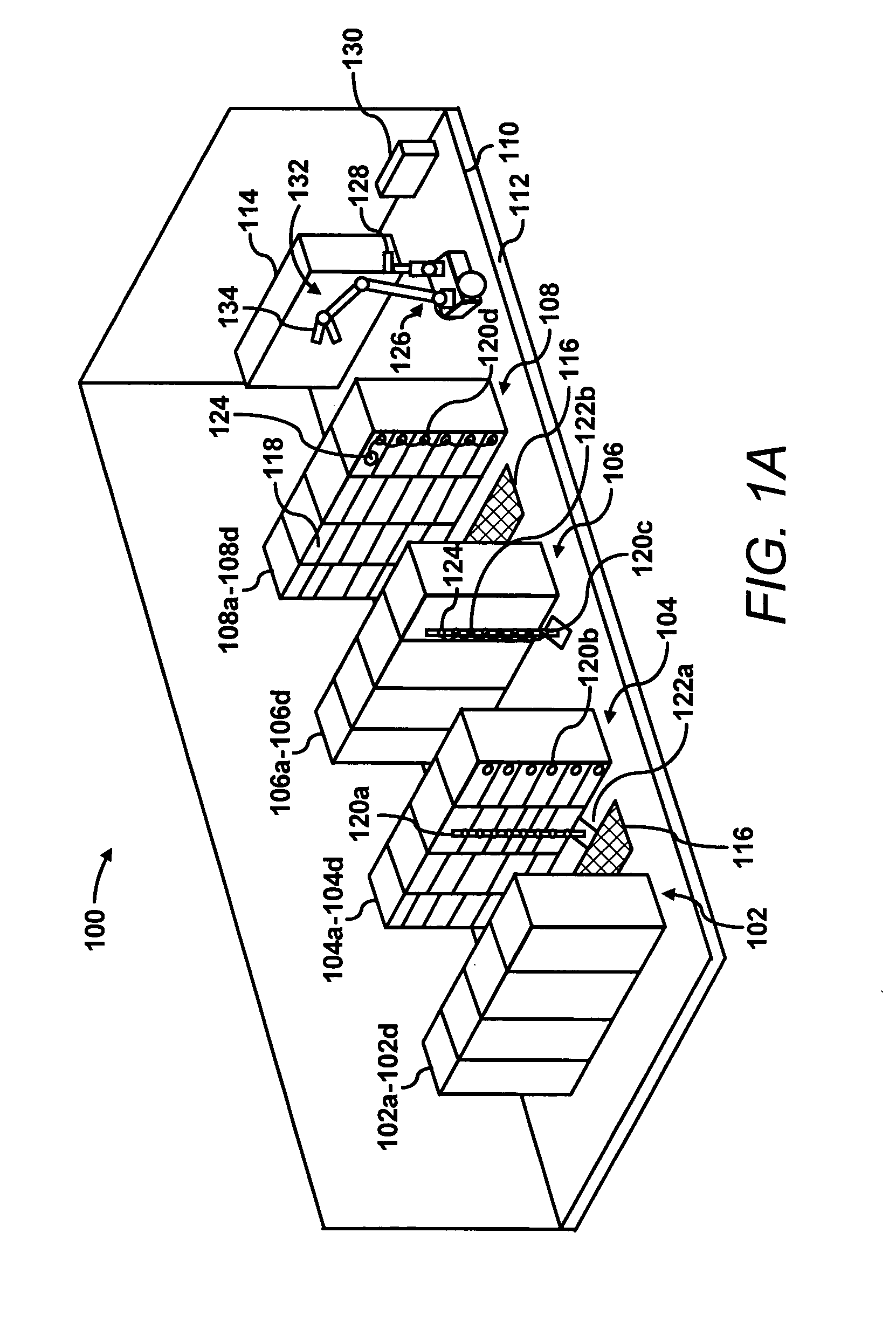
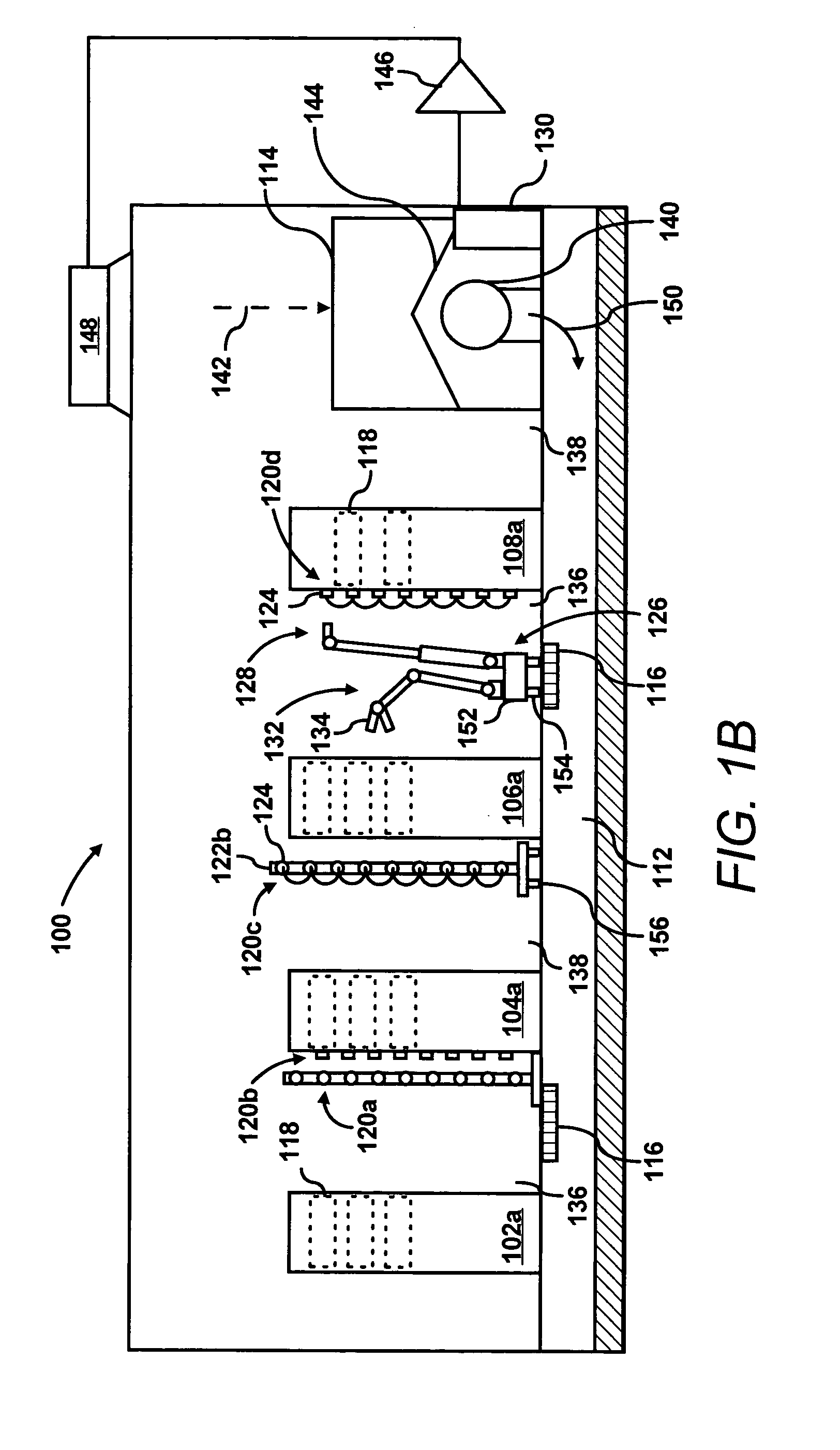
[0019] Throughout the present disclosure, reference is made to “cooling fluid” and “heated cooling fluid”. For purposes of simplicity, “cooling fluid” may generally be defined as air that has been cooled by a cooling device, e.g., an air conditioning unit. In addition, “heated cooling fluid” may generally be defined as cooling fluid that has been heated. It should be readily apparent, however, that the terms “c...


PUM


Abstract

A system for collecting data in a room. The system includes a plurality of sensor devices positioned at various locations in the room. The sensor devices include a sensor configured to detect at least one condition and a controller configured to control the sensor. The system also includes at least one data storage device configured to store the detected at least one condition and an interface mechanism for enabling communication of the stored at least one condition. The system further includes a data collector for interfacing with the interface mechanism to receive the stored at least one condition from the at least one data storage device.

Description

BACKGROUND OF THE INVENTION [0001] A data center may be defined as a location, for instance, a room, that houses computer systems arranged in a number of racks. A standard rack, for example, an electronics cabinet, is defined as an Electronics Industry Association (EIA) enclosure, 78 in. (2 meters) high, 24 in. (0.61 meter) wide and 30 in. (0.76 meter) deep. These racks are configured to house a number of computer systems, about forty (40) systems, with future configurations of racks being designed to accommodate 200 or more systems. The computer systems typically include a number of printed circuit boards (PCBs), mass storage devices, power supplies, processors, micro-controllers, and semi-conductor devices, that dissipate relatively significant amounts of heat during their operation. For example, a typical computer system comprising multiple microprocessors dissipates approximately 250 W of power. Thus, a rack containing forty (40) computer systems of this type dissipates approxim...

Claims


Application Information

Patent Timeline
IPC IPC(8): G05D1/02G05D23/19
CPCG05D1/0225G05D1/0234G05D1/0246G05D2201/0207G05D1/0282G05D23/193G05D1/0255G05D23/1932
Inventor BASH, CULLEN E.MOORE, DAVID A.PATEL, CHANDRAKANT D.
Owner HEWLETT-PACKARD ENTERPRISE DEV LP
Why Eureka
Try Eureka