Boot band

a technology of boot straps and bands, applied in the direction of hose connections, couplings, mechanical equipment, etc., can solve the problems of excessive clamping of the boot, deterioration of sealing properties, and increased load on the boot, so as to shorten the length of the boot straps, prevent the effect of boot breaking and wide range of tolerances

Inactive Publication Date: 2005-08-11
NHK SPRING CO LTD
View PDF5 Cites 7 Cited by
  • Summary
  • Abstract
  • Description
  • Claims
  • Application Information

AI Technical Summary

Benefits of technology

[0008] The boot-band of this invention can clamp a boot while maintaining a clamping condition on the boot by exercising the clamping force in a way so as to shorten the boot-band's length under a condition that the belt-like boot-band is shaped like a ring.
[0009] In the invention of claim 1, because, at the time of clamping, both the smaller-cross-sectional area and the general part are elongated by plastic deformation, a wide range of tolerance can be obtained. In addition, because the boot is not excessively clamped at the plastic deformation area, breakage of the boot can be prevented. Also, because both the smaller-cross-sectional area and the general part are elongated, elongation does not need to be borne only by the smaller-cross-sectional area. Thus, the smaller-cross-sectional area does not need to be elongated, adhesiveness to the boot can be secured, and stable and good sealing becomes possible.
[0013] Condition 1 of the invention of claim 2 is a condition for elongating the belt-shaped general part by plastic deformation, and Condition 2 is a condition for preventing breakage of the smaller-cross-sectional area. Accordingly, when said Conditions 1 and 2 are satisfied, the invention of claim 2 can have the same effects as the invention of claim 1.
[0015] When the smaller-cross-sectional area is formed by processing such as punching, the smaller-cross-sectional area hardens at the time of processing. According to the invention of claim 3, because Condition 2 is set taking into consideration (1) the rate of change of the yield point, with said rate varying according to the hardening process, and (2) the cross-sectional area of the smaller-cross-sectional area, the adhesiveness force can act on the boot even more effectively.

Problems solved by technology

H8-170773 is elongated at the elastic area, the load on the boot is increased, as a result of which the boot might be excessively clamped and might even be broken.
However, because adhesiveness to the boot is reduced at the opening-formation part when the opening is made long, the clamping force at the opening-formation part is insufficient, and as a result the sealing property is deteriorated and grease leakage occurs, which creates problems.
As described above, a conventional boot-band only adjusts tolerance, and it can neither prevent breakage of the boot nor provide a stable and secure sealing.

Method used


Image

  • Boot band
  • Boot band
  • Boot band

Examples


embodiment 1

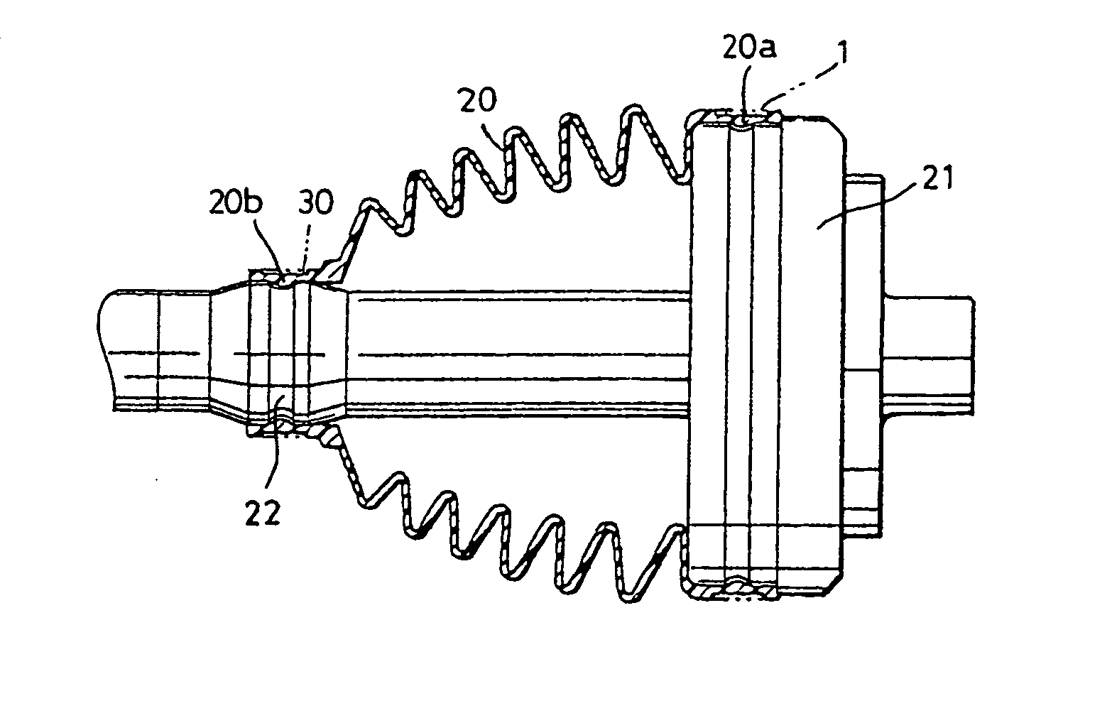
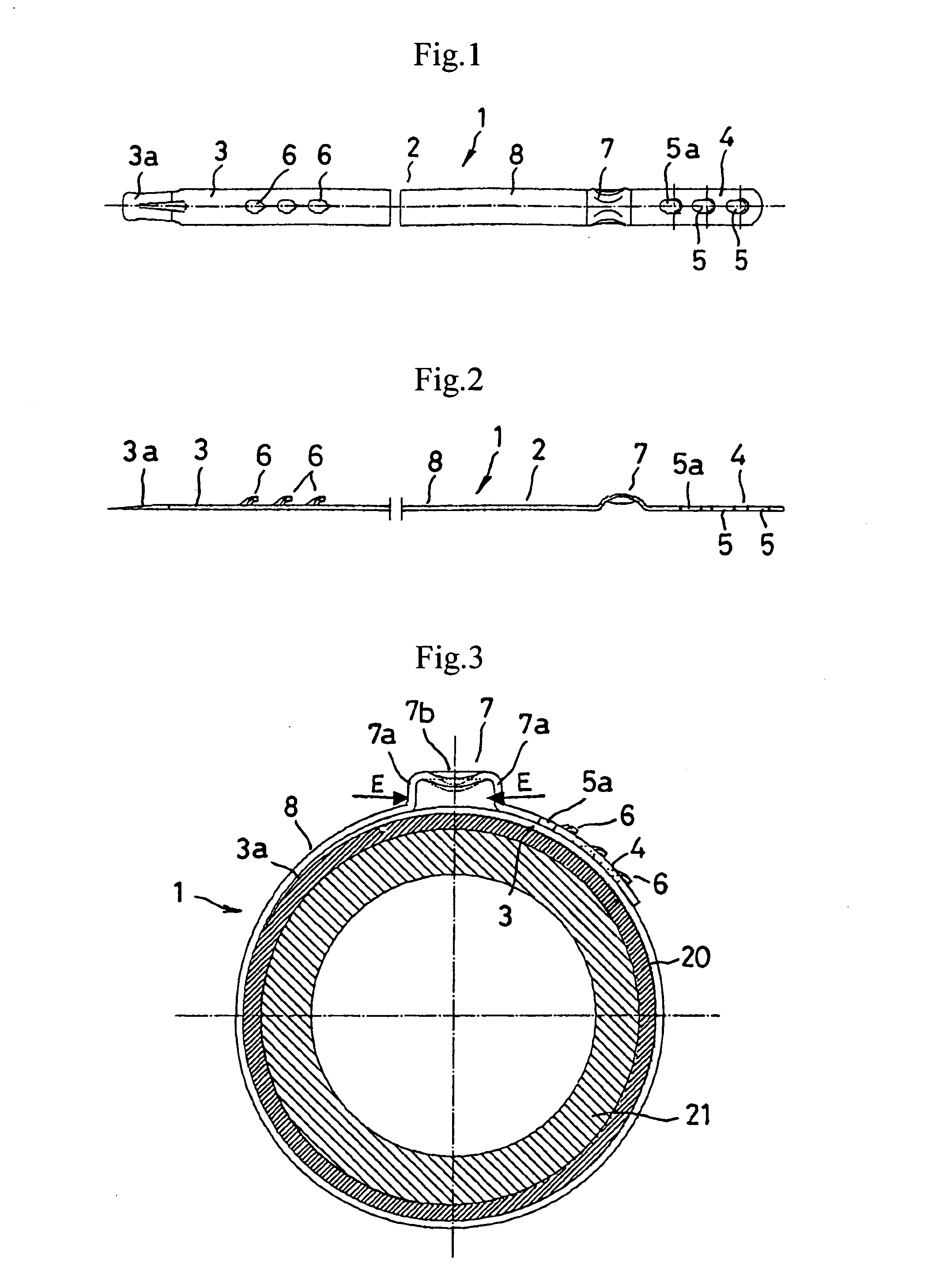
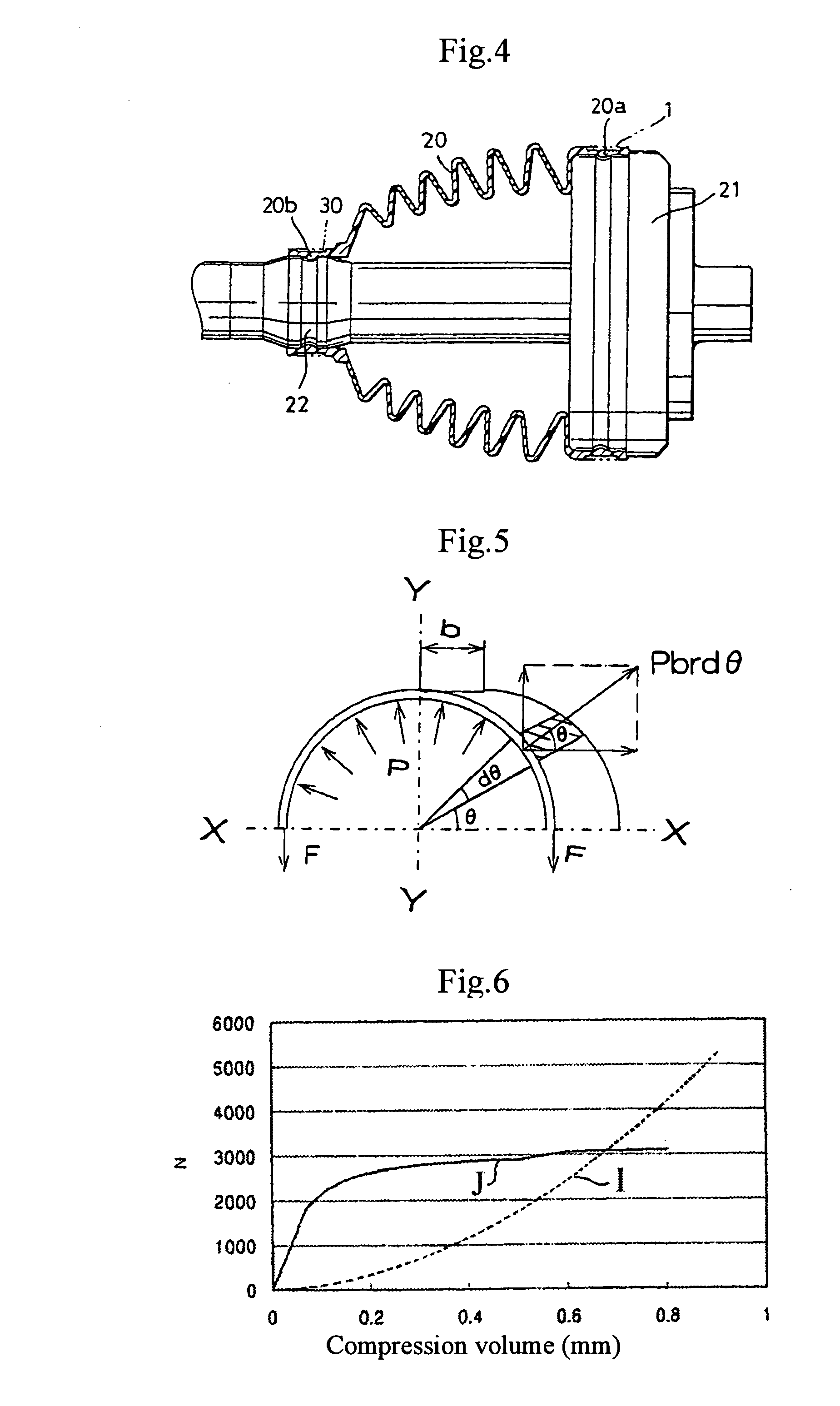
[0036]FIGS. 1 through 8 relate to a boot-band 1 in Embodiment 1 of the present invention. FIG. 1 is a plan view of the boot-band FIG. 2 is a side elevation view thereof; and FIG. 3 is a cross-sectional view of a boot-band 1 when it is wound around a boot 20.

[0037] The boot-band 1 has a belt-shaped member 2 that is made of a metal such as stainless steel, and that is formed into a thin horizontal shape. As shown in FIG. 3, the belt-shaped member is wound around the boot 20 so as to surround the boot 20 like a ring. At the time of winding, the belt-shaped member 2 is in such a condition that an outer portion 4 is overlapped onto the inner portion 3 of the belt-shaped member 2 that is in contact with the outer periphery of the boot 20. In addition, as shown in FIG. 4, the boot 20 is used so as to cover a metallic member 21 such as a shaft.

[0038] A plurality (three in this embodiment) of engagement holes 5 (in FIGS. 1 and 2), 5a (in FIGS. 1, 2, and 3) are formed in the outer overlap p...

embodiment 2

[0069]FIGS. 9 through 12 show a boot-band 30 in Embodiment 2. The boot-band 30 in this embodiment is constituted such that an opening 31 is formed in the boot-band 1 of Embodiment 1.

[0070] The opening 31 is formed as a rectangular shape, positioned adjacent to the ear portion 7 of the belt-shaped member 2. When the belt-shaped member 2 is wound like a ring, as shown in FIG. 11, the opening 31 is positioned in the outer overlap portion 4, and it does not contact the boot 20. Accordingly, the opening 31 does not bite into the boot 20. The opening 31 is formed by punching at a predetermined portion of the belt-shaped member 2, and the opening 31 serves as a smaller-cross-sectional area that elongates when the boot-band 30 is clamped.

[0071] In this embodiment, as is similar to Embodiment 1, a plurality of engagement holes 5, 5a are formed on the outer overlap portion 4 of the belt-shaped member 2, and a plurality of engagement prominences 6 that are to be engaged with the engagement h...

embodiment 3

[0086]FIGS. 13 through 17 show a boot-band 40 in Embodiment 3. On the side of the outer overlap portion 4 of the boot-band 40, a lock hole 41, a projection 45, and a tack hole 43 are formed in that order from the opening-side end (the left end in FIGS. 13 and 14) in a lengthwise direction (to the right). Also, on the side of the inner portion 3 of the belt-shaped member 2, a projection 46, a locking projection 42, and a connecting projection 44 are formed in that order from the side of the outer overlap portion in the lengthwise direction (to the right).

[0087] By the clamping action of the boot-band 40, the lock hole 41 and the locking projection 42 are engaged with each other and maintain a clamping condition; these therefore act as a clamping means. The tack hole 43 and the connecting projection 44 are engaged with each other, so that the belt-shaped member 2 is temporarily tacked in a ring-shape condition. Also, as the tack hole 43 is formed into a rectangular shape, it acts to ...


PUM


Abstract

A boot-band that (a) does not excessively clamp a boot, (b) can prevent leakage of grease from the boot and the boot-band, and (c) uniformly produces a tight contact force on the boot without deteriorating the contact force on the boot. This boot-band includes a metallic belt-shaped member (2), and its clamping force, which is generated in the direction that shortens the circumference of the metallic belt-shaped member (2), is exercised under a ring-shaped condition in such a way that one end of the metallic belt-shaped member overlaps the other end thereof, and in such a way that both ends are wound around the outer periphery of the boot. A smaller-cross-sectional area (5a) is formed in a part of the belt-shaped member (2); the smaller-cross-sectional area (5a) and the general part (8), whose cross-sectional area is not reduced, are elongated due to plastic deformation caused by the clamping force.

Description

FIELD OF THE INVENTION [0001] This invention relates to a boot-band, such as one made of rubber, resin, or the like, that is used for fixing a boot on a connecting member. BACKGROUND OF THE INVENTION [0002] A boot-band is used for fixing onto a metallic member a boot that is hooked between metallic members such as a power-transmission shaft. It is used, for example, for a constant-velocity joint and the like of an automobile. In a constant-velocity joint of an automobile, a boot is hooked between shafts while holding grease inside, and the boot is clamped from the outside by the boot-band and brought into close contact with the shaft in order to prevent the grease from flowing outside between the boot and the shafts. [0003] Because such boots, shafts, and boot-bands might have dimensional errors at the time of manufacturing, the tolerance thereof needs to be made acceptable. A boot-band that has acceptable tolerance is disclosed in Japanese Unexamined Published Patent Application No...

Claims


Application Information

Patent Timeline
Patent Type & Authority Applications(United States)
IPC IPC(8): F16L33/02F16D3/84F16J3/04F16J15/52F16L33/025
CPCF16L33/025F16L33/035Y10T24/1482Y10T24/1478Y10T24/1457F16D3/845
Inventor OGINO, TAKASHI
Owner NHK SPRING CO LTD
Why Eureka
Try Eureka