Permanent magnet for motor, motor and magnetizing method

a permanent magnet and motor technology, applied in the field of motors, can solve the problem that the inherent ability of magnetic materials cannot be completely brought ou

Inactive Publication Date: 2005-08-11
SEIKO INSTR INC
View PDF5 Cites 34 Cited by
  • Summary
  • Abstract
  • Description
  • Claims
  • Application Information

AI Technical Summary

Benefits of technology

[0021] The present invention provides, in order to attain the above-mentioned object, a permanent magnet for a motor, which is disposed in a rotor for the motor and has a cylindrical shape, including domains that are magnetized in a radial direction and are arranged at regular intervals in a circumferential direction, ch

Problems solved by technology

As a result, there is a problem that full magnetization (magnetic saturation) for the permanent magnet i

Method used


Image

  • Permanent magnet for motor, motor and magnetizing method
  • Permanent magnet for motor, motor and magnetizing method
  • Permanent magnet for motor, motor and magnetizing method

Examples


embodiment

(1) Outline of Embodiment

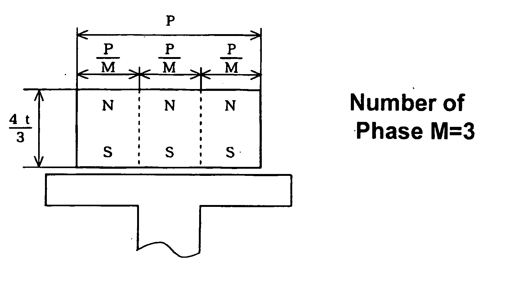
[0040] If a motor is downsized, a permanent magnet (having a cylindrical shape and provided to a rotor) used therefor is reduced in size. This requires a compact magnetizing head for magnetizing the permanent magnet and makes is difficult to allow current to flow in large amounts at the time of magnetization. As a result of suppressing current to be supplied to the magnetizing head (hereinafter, referred to as magnetizing current) at the time of magnetization, the permanent magnet is hardly magnetized to its limit of the magnetizing force (full magnetization). Thus, it is difficult to bring out an ability of the magnetic material fully.

[0041] Among others, in the case of using an outer rotor type motor, a magnetizing head for allowing magnetizing current to flow should be arranged inside a cylindrical magnetic material in order to magnetize the magnetic material from inside the same. In addition, a multipolar permanent magnet has been under study. Hence, th...


PUM

PropertyMeasurementUnit
Lengthaaaaaaaaaa
Magnetismaaaaaaaaaa

Abstract

The present invention relates to a cylindrical permanent magnet which is used in a micro DC brushless motor used in a compact hard disc etc. An Sm—Co based magnetic material is used as a magnetic material and the permanent magnet has domains magnetized in a radial direction and arranged at regular intervals in a circumferential direction. Provided that P represents a pitch corresponding to an average of an inner circumferential length and outer circumferential length in one of the domains, D denotes an inner diameter of the permanent magnet, t represents a thickness in the radial direction, N represents the number of domains, and M represents the number of AC phases for driving the motor, D is set to 20 (mm) or smaller and t is set to satisfy the relation of t≦πD/(NM−π).

Description

TECHNICAL FIELD [0001] The present invention relates to a motor, for example, a motor including a rotor provided with a permanent magnet. BACKGROUND ART [0002] In recent years, computers have been put in widespread use in a rapid pace. Disc-like storage media such as a hard disc and a magneto-optic disc are widely used for storage devices in most of those computers. Those storage media are rotated at a high speed by a small-sized motor provided to a disc drive and data is read or written from and to the media. [0003] The motor used for the disc drive is designed to generate a rotating magnetic field by means of a stator coil so as to act on a permanent magnet provided to a rotor, thereby rotating. [0004] The permanent magnet is magnetized radially (in a radial direction) and inverts polarities at a predetermined pitch along a circumferential direction. That is, the N pole and the S pole appear at regular intervals along an inner or outer circumference. The same polarity is attained ...

Claims


Application Information

Patent Timeline
IPC IPC(8): H01F1/053H01F13/00H01F41/02H02K1/27H02K15/03H02K21/22
CPCH01F13/003H01F41/028H02K1/2786Y10T29/49075H02K21/222Y10T29/49009H02K15/03H02K1/2791H02K1/27H01F7/02H01F13/00
Inventor TAKEHARA, ISAMUKINOSHITA, SHINJIGOTOH, HIROMITSU
Owner SEIKO INSTR INC
Why Eureka
Try Eureka