Metallic profile for the composition of structures for the assembly of cabinet/enclosures

a technology of structure composition and metal profile, which is applied in the direction of dismountable cabinets, substation/switching arrangement casings, other domestic articles, etc., can solve the problems of complicated industrial workability, technical restrictions, and impede the productive process, and achieve the effect of increasing the mechanic resistance of the profil

Inactive Publication Date: 2005-08-11
FRANCISQUINI MELQUISEDEC
View PDF6 Cites 27 Cited by
  • Summary
  • Abstract
  • Description
  • Claims
  • Application Information

AI Technical Summary

Benefits of technology

[0023] e) the three outside rims combine to permit, as mentioned above, the fixing of different components, such as: closing panels, doors (hinges), rubber sealing profile and / or others. Furthermore, an important detail is the geometry of the set of rims, which besides significantly increasing the mechanic resistance of the profile, also significantly favors the mechanical interconnection between one structure and another from any of its sides, thus completing its advantageous characteristics, including that of the modularity of the set.

Problems solved by technology

At present there are different types of structures, all obtained with metallic profiles, which in most cases are shaped in sheet bending presses, which hinders the productive process and presents some technical restrictions.
However, as far as seals are concerned, they require special technical embodiments depending on the application, and they also present complicated industrial workability, since like what happens in the profile described in the aforementioned document (PI 8.406.283)—rack board for a distribution cabinet filed on Dec. 7, 1984, it is used exclusively for the assembly of indoor cabinets / enclosures.
In this manner, the sealing promoted by the actual construction of the profile is completely destroyed, which makes the application of the structure when it is for use in an outdoor cabinet unfeasible.
On the other hand, taking into consideration the geometry of the aforementioned profile, the sealing (72) is of the cord type, which can be applied in different ways, by gluing or by deposition of material applied directly on the closing panel or door, thus generating other disadvantages, mainly a higher cost, besides which the sealing will always be an integral part of the closing panel or door and, due to the flexibility of such parts, the sealing pressure is not always uniform.
Another problem noted is that in the event of possible damage to such seals, the repair implies the substitution of the closing panel or door.
Thus, in brief, we can say that the inconveniences of the profiles of the state of the art are generated according to the geometry adopted for them, and by the different openings applied to their walls.

Method used


Image

  • Metallic profile for the composition of structures for the assembly of cabinet/enclosures
  • Metallic profile for the composition of structures for the assembly of cabinet/enclosures
  • Metallic profile for the composition of structures for the assembly of cabinet/enclosures

Examples


first preferred embodiment

[0058]FIG. 16A exhibits the first preferred embodiment for the profile in question, maintaining practically the same transversal geometry although in this case it is characterized by the fact that its rim (15a) is formed at the exact point defined by the vertex (107), in a coplanar position in relation to the wall 107b and perpendicular to the wall (107a).

second preferred embodiment

[0059]FIG. 16B exhibits the second preferred embodiment for the profile in question, maintaining practically the same transversal geometry although in this case it is characterized by the fact that its rim (111), formed by two walls (110), has its end or free edge perpendicularly folded outwards (113a). In this case, if this profile is positioned at the bottom or top of the cabinet / enclosure, the aforementioned rim or end (113a) forms a square like a frame to support the bottom or top of the cabinet / enclosure, thus eliminating the use of complements to fix and support such parts of the cabinet / enclosure, whereas when this is necessary, said rim would also provide conditions for the configuration of a complementary compartment at the bottom or top of the cabinet / enclosure.

third preferred embodiment

[0060]FIG. 16C exhibits the third preferred embodiment for the profile in question, maintaining practically the same transversal geometry illustrated in FIG. 16B, although in this case it is characterized by the fact that its end (112a) is perpendicularly folded outwards like the end (113a), so that this end (112a) can cater to other assembly situations of some sealing components and others located outside the cabinet / enclosure.


PUM


Abstract

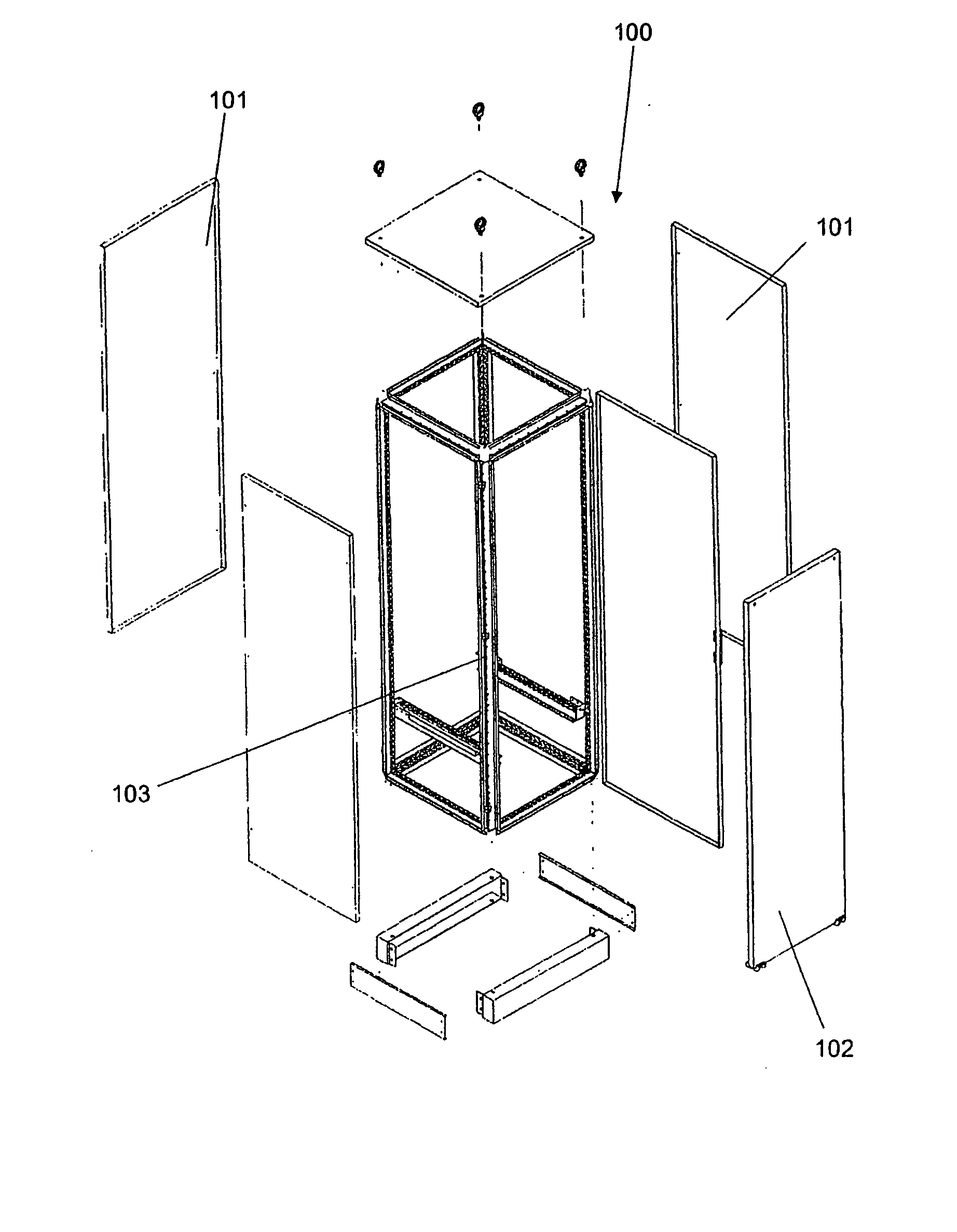
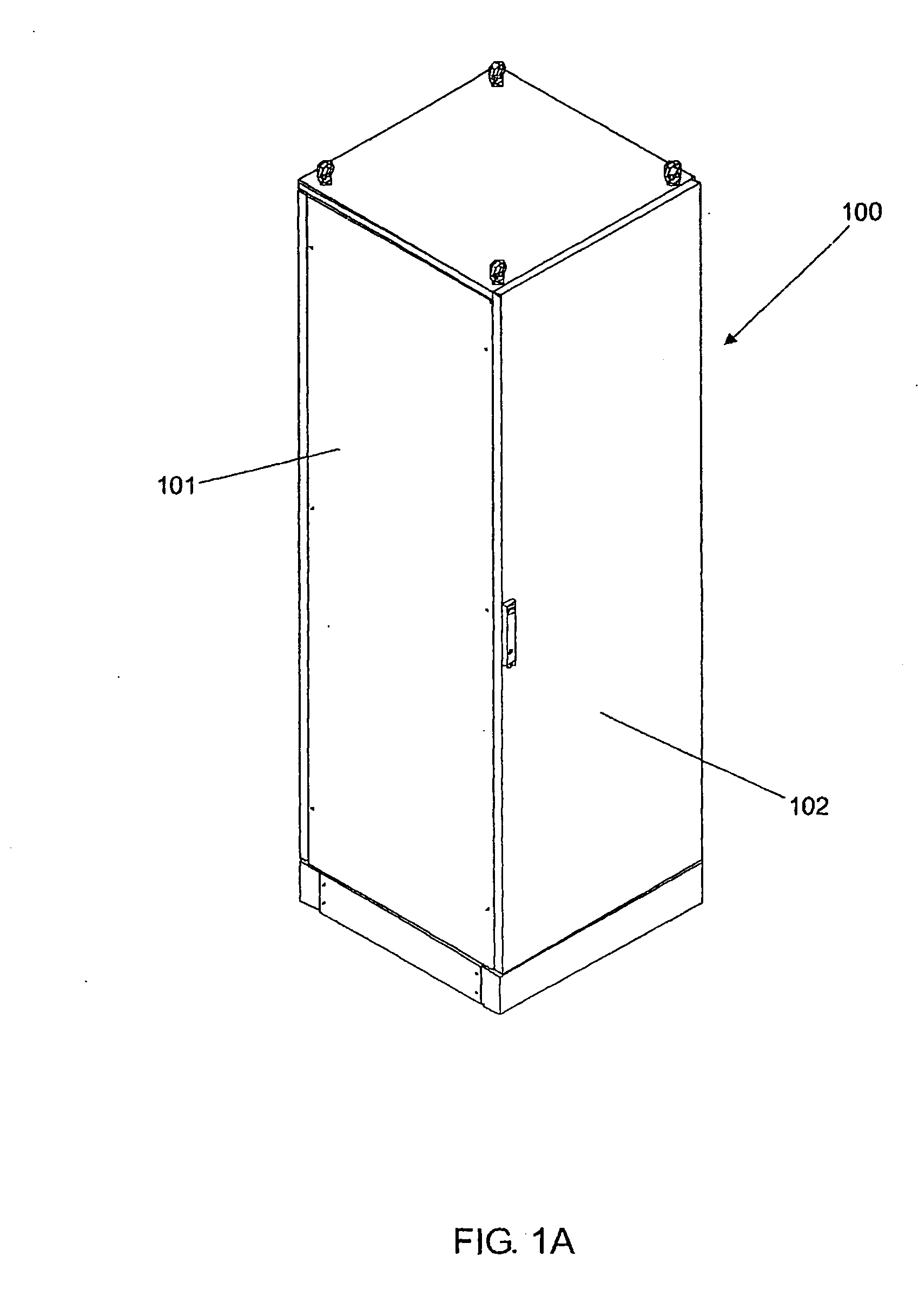
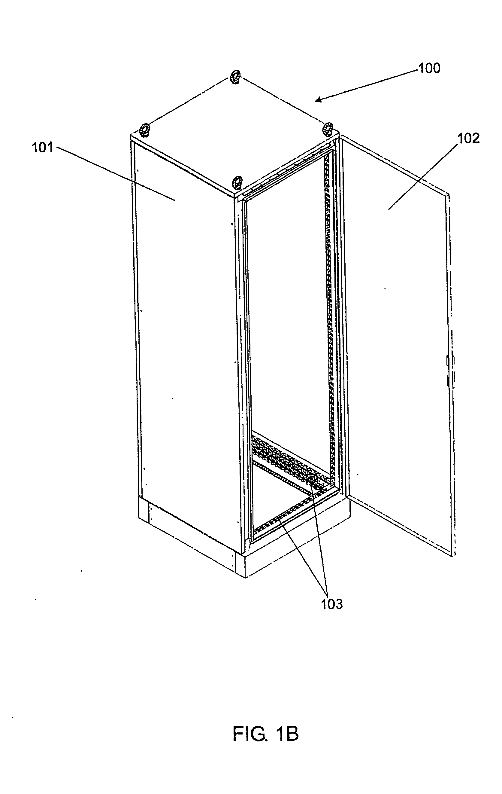
Comprehending a profile (104) that, from the outside, constitutes the means of support for the closings and accessories, while on the inside, the same structure configures the struts for the assembly of components and electric and electronic devices, in addition to which this profile (104) presents a cross section with a geometry defined by a central core in the tubular shape with a quadrangular section (105), where the vertex (106) is oriented to the inside of the cabinet (100), while the opposite vertex (107) is oriented to the outside of this cabinet (100), and these two vertexes are formed by single walls, which does not apply to the other two remaining vertexes (108) and (109), which are defined by the junction of the sheet that forms the first two vertexes (106-107) and from this point on, the double walls (110) are extended in a coplanar position in relation to the adjacent walls (106a-106b) of the vertex (106), forming opposite rims (111a 111b), whose ends are perpendicularly folded forming short ends (112) and (113) which, besides being grooved (114), are also distanced in parallel from the adjacent walls (107a-107b) of the vertex (107), whose wall (107a) includes a projection perpendicularly oriented to the outside, configuring a perpendicular rim (115), finalizing the configuration of a profile that permits the assembly of structures (103) which, in turn, receives different closings (101) and doors (102), configuring cabinets/enclosures or boxes (100).

Description

TECHNICAL FIELD [0001] More specifically, this Invention refers to a singular accomplishment in the geometry of a metallic profile especially developed for the assembly of structures normally used in a wide variety of types of cabinets / enclosures, which are also known as panel boards, and are actually metallic boxes (cabinets) with doors and side closings used to house a very large variety of components and electric and electronic devices. STATE OF THE ART [0002] As is known by those skilled in this art, at present there are different types of cabinets / enclosures also called switchboards, panel boards or boxes, designed to contain various components and electric and electronic devices in a very wide variety of fields of activity, including the telecommunications sector. [0003] Hence in different situations of electrical distribution or assembly of components and electric and electronic devices, the use of a box, cabinet or panel is extremely important. [0004] Although there is a ver...

Claims


Application Information

Patent Timeline
Patent Type & Authority Applications(United States)
IPC IPC(8): H05K7/18H02B1/00H02B1/01H02B1/30H05K7/00
CPCH02B1/01H02B1/308H02B1/28H02B1/013H02B1/301
Inventor FRANCISQUINI, MELQUISEDEC
Owner FRANCISQUINI MELQUISEDEC
Why Eureka
Try Eureka