
Protective glove

a glove and glove technology, applied in the field of protective gloves, can solve the problems of insufficient deceleration of bullets in the thin layer of the known clothing, the user's touch or feeling is restricted by the items of protective clothing, and the relatively high production cost of clothing items, etc., to achieve convenient attachment to the lining, increase the functionality of the glove, and facilitate the storage of space in the protective padding

Inactive Publication Date: 2009-05-21
ESKA LEDERHANDSCHUHFAB & CO
View PDF11 Cites 16 Cited by
  • Summary
  • Abstract
  • Description
  • Claims
  • Application Information

AI Technical Summary

Benefits of technology

[0011]The resultant advantage primarily resides in the fact that, by providing one or more free zone(s) starting from the edge or side regions of the protective padding in which the protective padding and lining are not joined, a user is able to move parts of his hand, in particular his fingers, in the free zone without there being a significantly increased mechanical resistance, thereby requiring less force to be expended. Accordingly, a protective padding with a particularly high protective effect can be used which is significantly more dimensionally stable and bending-resistant than the flexible lining but does not or barely restricts the freedom of movement of a user's hand because the protective padding extends in the free zone independently of and standing free from the lining of the protective glove surrounding a user's band. The advantage of a glove based on this type of design is that it affords greater and better protection against foreign bodies in the most important protective zones and the required freedom of movement and sense of touch and feeling in the regions outside the protective zone, such as the palm of the hand for example, is not restricted.
[0026]Other advantageous embodiments of the protective glove may include straps or tape, and in spite of the fact that protective padding is provided, the adjusting mechanism, in particular the strap, enables the protective glove to be reliably affixed to a user's hand, thereby preventing the glove from being undesirably pulled off. This is rendered possible in particular by the tunnel provided in the protective padding, through which the strap extends, and the shaft can be secured around a wide circumference in the wrist region of a user's hand.

Problems solved by technology

With items of clothing of this structure, even though the lining incorporating the protective material may be relatively thin, a user's sense of touch or feeling is restricted by these items of protective clothing compared with a conventional item of clothing that does not incorporate bullet-proof or stab-resistant protective material.
Such items of clothing are also relatively expensive to produce and because of their thin-layered structure, reliable protection against bullets can be guaranteed to only a certain degree.
Although bullets impacting with the known protective clothing may be prevented from penetrating the interior of the known protective clothing, the thin-layered material structure of the known clothing does not decelerate bullets sufficiently and the kinetic energy of ballistic missiles can not be sufficiently absorbed by this material structure to prevent a trauma effect and impact injuries to a user caused by the forces released on impact.
It should be pointed out that when it comes to protective clothing known from the prior art, protective gloves in particular are not satisfactory in practical applications because a user's sense of touch and feeling and the freedom of movement of the fingers, which is crucial to some activities, is too severely restricted due to the protective material in these regions since it is not readily deformable.

Method used


Image

  • Protective glove
  • Protective glove
  • Protective glove

Examples


Embodiment Construction

[0033]Firstly, it should be pointed out that the same parts described in the different embodiments are denoted by the same reference numbers and the same component names and the disclosures made throughout the description can be transposed in terms of meaning to same parts bearing the same reference numbers or same component names. Furthermore, the positions chosen for the purposes of the description, such as top, bottom, side, etc, relate to the drawing specifically being described and can be transposed in terms of meaning to a new position when another position is being described. Individual features or combinations of features from the different embodiments illustrated and described may be construed as independent inventive solutions or solutions proposed by the invention in their own right.

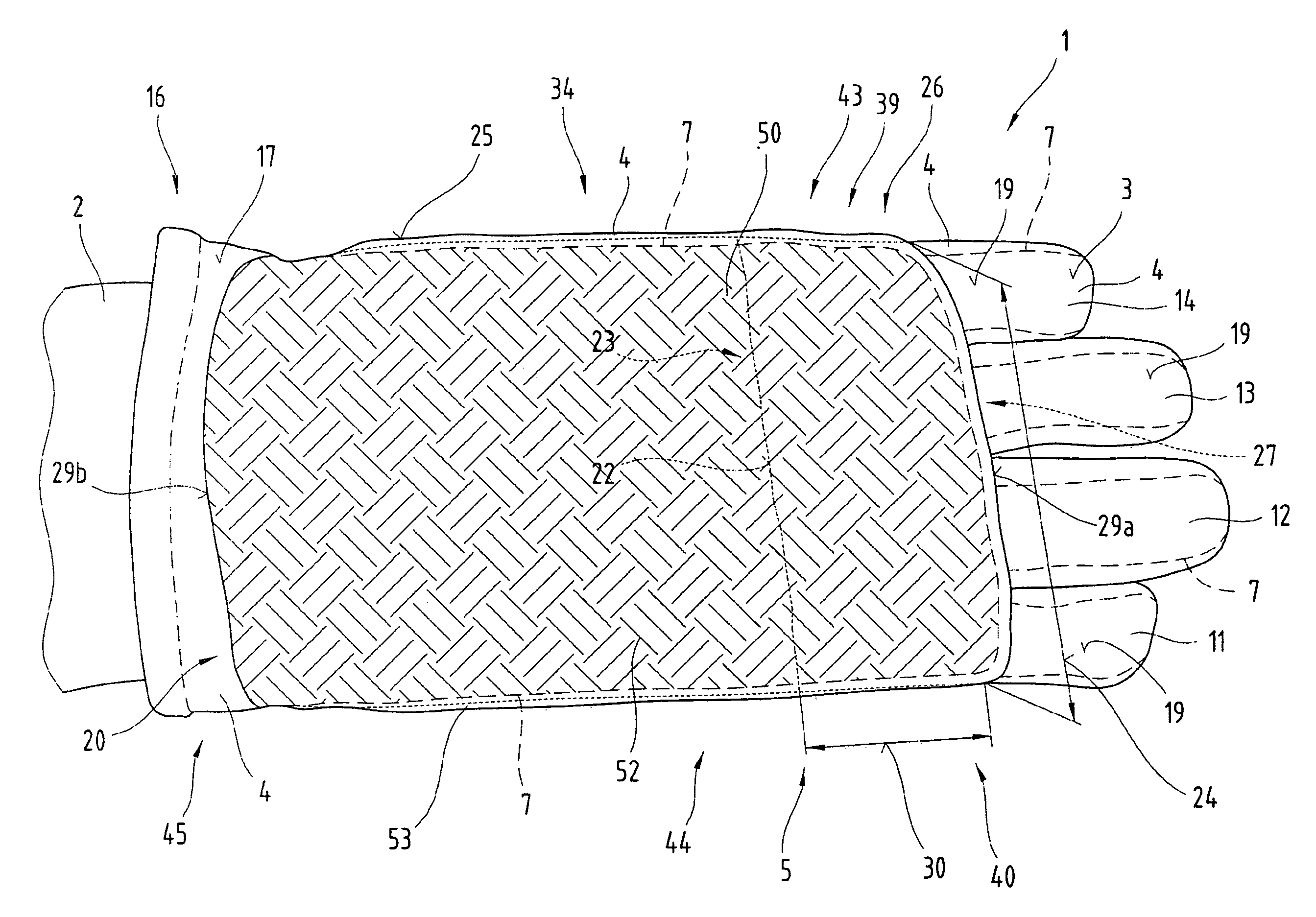
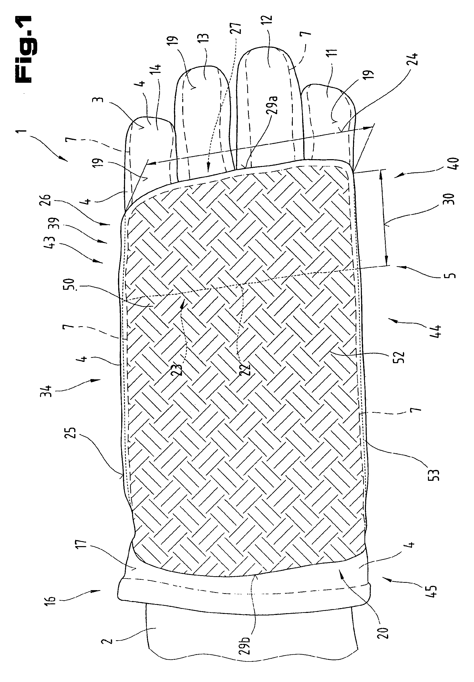
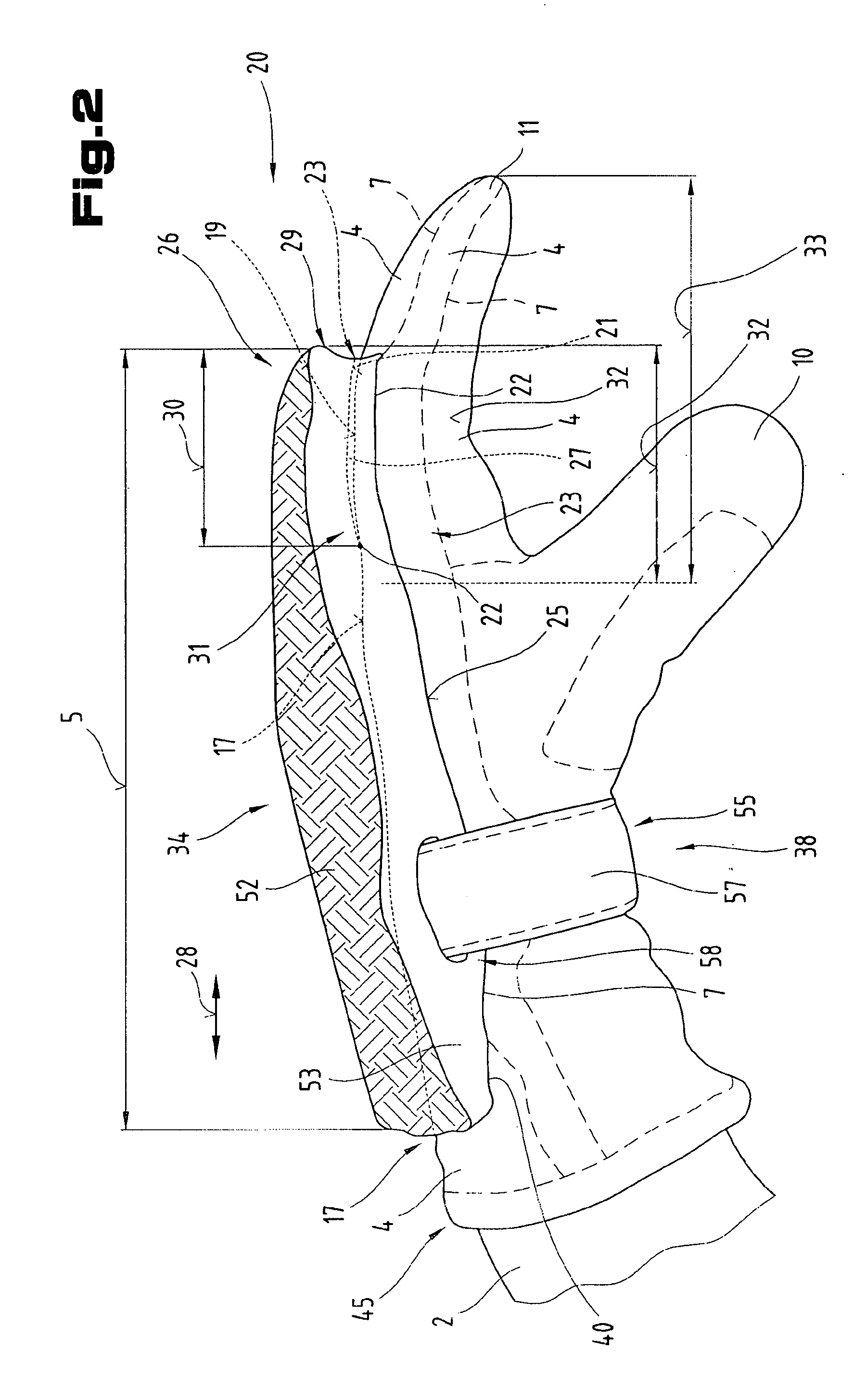
[0034]FIGS. 1 to 5 illustrate one possible embodiment of a protective glove 1. The protective glove 1 is designed to protect certain regions of a user's hand 2 against foreign bodies hitting t...


PUM


Abstract

The invention relates to a protective glove (1) for protecting certain regions of a user's hand (2) against foreign bodies impacting with it such as bullets and / or stabbing or cutting devices, with a lining (4) made from a material that is not or not very resistant to stabs, cuts or incisions and is not bullet-proof, for example a textile fabric, a leather, a laminate or similar, comprising several glove fingers (10 to 14), and a glove top face (17) extends on an external surface (3) of the lining (4) in the region of finger top sides (19) and in a top hand region (15), and a bullet-proof and / or cut or stab inhibiting protective padding (20) is built up on or placed on certain regions of the glove top face (17) starting from a padding bottom face (21) and is attached to the lining (4) at joining points (22), and the protective padding (20) prevents penetration by foreign bodies impacting with it to a glove interior lying underneath it.

Description

CROSS-REFERENCE TO RELATED APPLICATIONS[0001]This is a national phase application of PCT Patent Application No. PCT / AT2005 / 000349, filed Aug. 31, 2005 which claims priority from Austrian Application No. A 1520 / 2004, filed Sep. 13, 2004. The disclosure of each such application is hereby incorporated by reference in its entirety where appropriate for teachings of additional or alternative details, features, anchor technical background, and priority is asserted from each.BACKGROUND OF THE INVENTION[0002]The invention relates to a protective glove for protecting a user's hand from foreign bodies, such as projectile objects or stabbing or cutting devices, of the type described in the introductory part of claim 1.[0003]Items of clothing designed to project against stabbing and shooting injuries are already known from the prior art. The linings of these items of clothing are usually made up of several layers of material and individual layers are made from a bulletproof material or a materi...

Claims


Application Information

Patent Timeline
Patent Type & Authority Applications(United States)
IPC IPC(8): F41H1/02A41D13/08A41D19/00
CPCF41H1/00A41D19/01505
Inventor LOOS, PAUL
Owner ESKA LEDERHANDSCHUHFAB & CO
Learn More