Optical information recording method, optical information recording device, and optical information recording medium

a technology of optical information and recording medium, which is applied in the field of optical information recording medium, can solve the problems of excessive time taken for recording and reproduction apparatus to come to a state, affecting the shape of recording marks, and different thermal characteristics of optical disks, so as to reduce the time required to determine recording parameters

Inactive Publication Date: 2005-08-11
PANASONIC CORP
View PDF13 Cites 33 Cited by
  • Summary
  • Abstract
  • Description
  • Claims
  • Application Information

AI Technical Summary

Benefits of technology

[0036] According to this medium, since it is possible to test record by changing the correction accuracy of the correction table according to the identification re...

Problems solved by technology

Coincidentally, in the case of the mark edge recording method, differences in thermal characteristics of optical disks affect the shape of the recording mark itself, and the degree of thermal interference between recording marks.
Thus, if, for example, the thermal interference of an optical disk is small, and it is not necessary to correct the front end pulse edge position and the back end ...

Method used


Image

  • Optical information recording method, optical information recording device, and optical information recording medium
  • Optical information recording method, optical information recording device, and optical information recording medium
  • Optical information recording method, optical information recording device, and optical information recording medium

Examples


embodiment 1

Operation of Embodiment 1

[0069] The following is a description of the operation of the recording and reproduction device of the present embodiment using the flowchart in FIG. 4 and operational charts in FIG. 5 to FIG. 7.

[0070]FIG. 4 is a flowchart showing the operation of the present embodiment. FIG. 5 is a waveform showing the operation according to the present embodiment when recording at an increased recording density. The operation to correct the edge positions of the front end pulse and the back end pulse in the combinations (that is, the elements of the correction table) of (pre-code length 7T—recording code length 3T—post-code length 7T), (pre-code length 7T—recording code length 5T—post-code length 7T) and (pre-code length 3T—recording code length 5T—post-code length 6T) is described in FIG. 5. Here, T represents the period of the channel clock. In FIG. 5, (a) is a channel clock signal, (b) is a waveform of the recording data signal 18, (c) is a waveform of the recording pu...

embodiment 2

Structure and Operation of Embodiment 2

[0118]FIG. 8 shows a perspective view of an optical disk1 (optical information recording medium) that is used in the present embodiment. In order to describe an internal portion of the optical disk, FIG. 8 shows the optical disk 1 with one part cut out. The optical disk is viewed from the side on which the laser light for recording and reproducing the optical disk is incident, and is made of a first information layer 801, which is positioned at the front, and a second information layer 802, which is positioned at the back. An identifier 305 is present independently on the information layers, and an identifier that corresponds to the correction accuracy is recorded.

[0119] Excluding the point that the identifier detection circuit detects the identifier on each information layer, the configuration and operation of the recording and reproduction apparatus of the present embodiment is the same as that of Embodiment 1.

embodiment 3

[0133] The present embodiment is an embodiment in which a disk whose recording conditions are identified by reproducing an identifier on the disk, and whose recording characteristics when, for example, the linear velocity of recording onto the disk is low, are such that even if the edge of the recording pulse is greatly changed then the effect on the edge position of the recording mark is small, and there are no unnecessary test recording steps to pass through by reducing the resolution of the elements of the correction table to record.

Configuration and Operation of the Embodiment 3

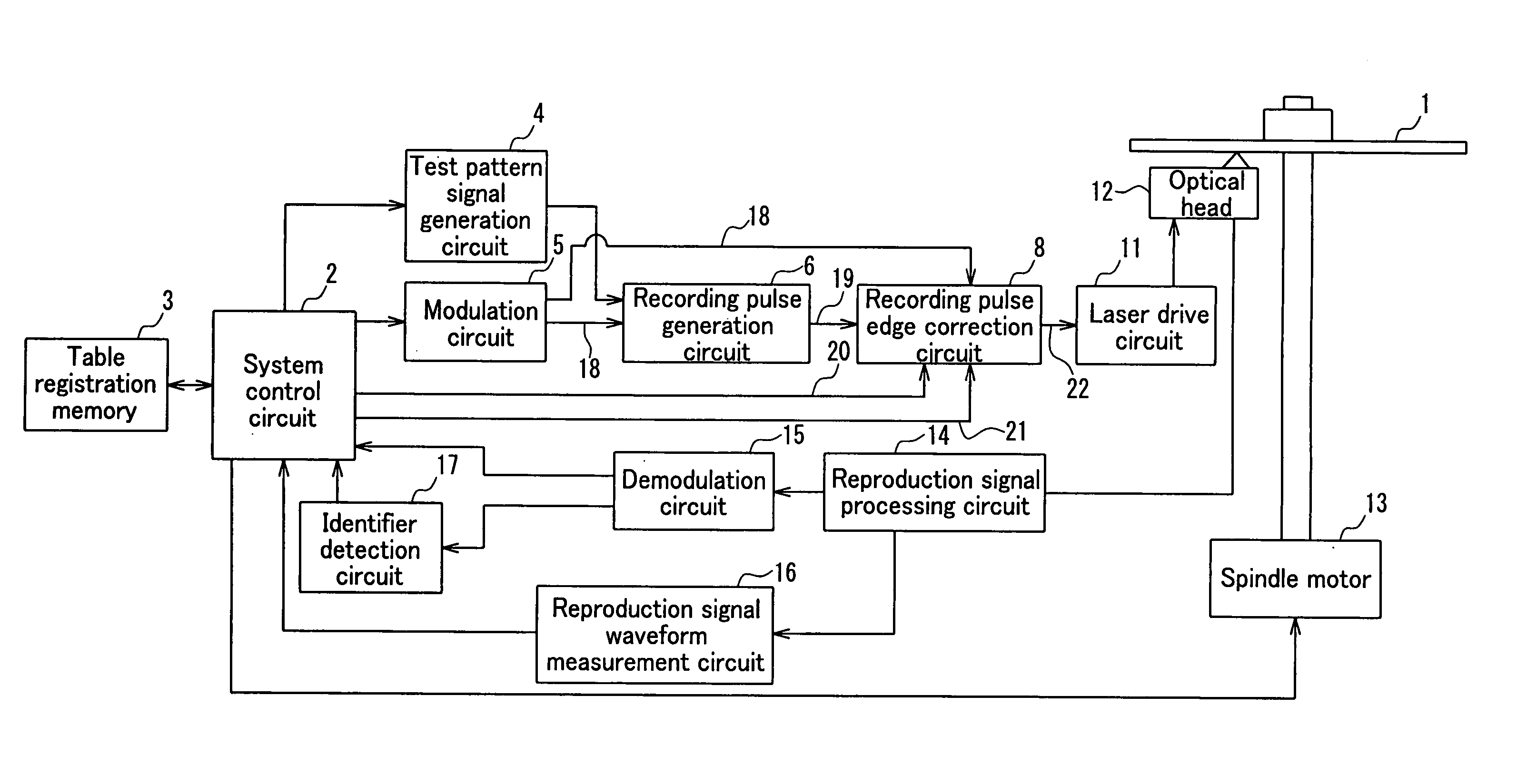
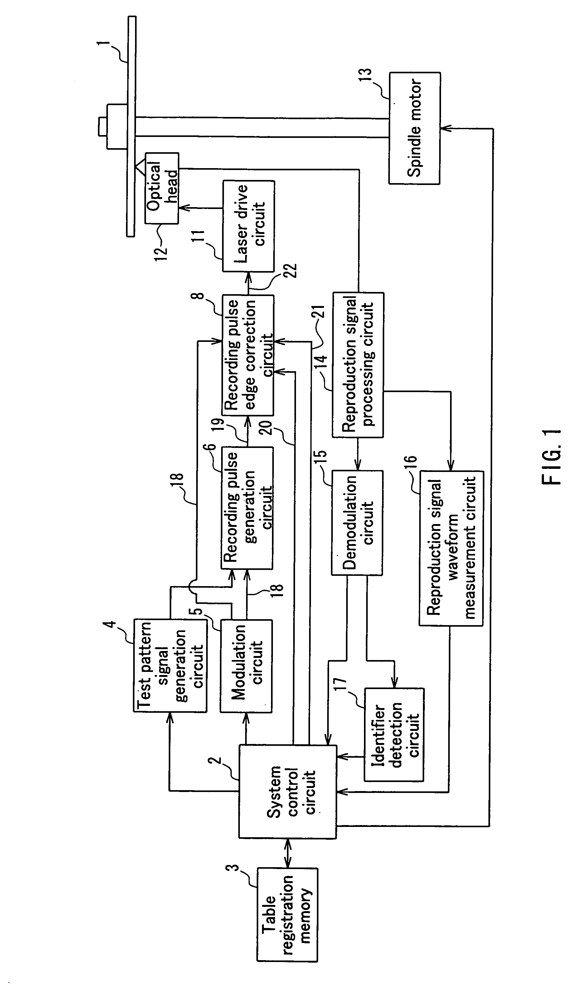
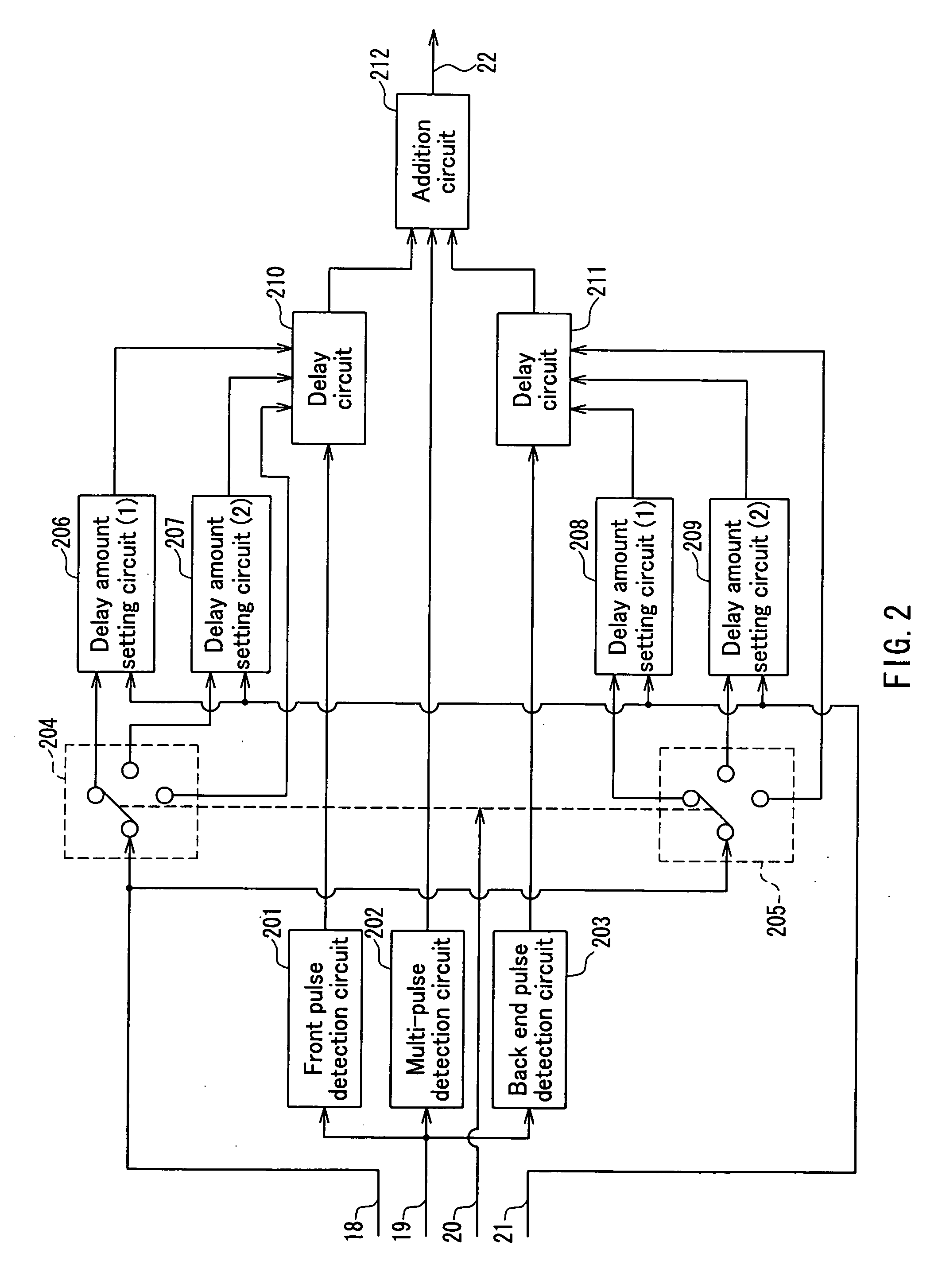
[0134] A structural overview of the recording and reproduction apparatus (optical information recording apparatus) for realizing Embodiment 3 is the same as that in FIG. 1. FIG. 9 is a diagram showing the detailed configuration of the recording pulse edge correction circuit 8 in FIG. 1. FIG. 10 is a flowchart used to describe the operation of the present embodiment, and FIG. 11 is a waveform diagram of...


PUM


Abstract

The present invention provides an optical information recording apparatus and method capable of effectively determining appropriate recording parameters in a short time with favorable efficiency, when recording information onto an optical disk having different information recording conditions and information recording characteristics. An information recording condition or an information recording characteristic of an optical disk 1 is identified, and a recording pulse position is corrected at a correction accuracy according to the identifies information recording condition or information recording characteristic, such that a recording mark is formed in a predetermined position.

Description

TECHNICAL FIELD [0001] The present invention relates to optical information recording media, such as optical disks, for optically recording and reproducing information, and information recording methods and information recording apparatuses that use the optical information recording media. BACKGROUND ART [0002] In recent years, optical disks, optical cards and optical tapes and the like have been proposed and developed as media for optically recording information. Of these, optical disks have come in for particular attention as media that are capable of recording and reproducing information, both in large volumes and at high density. A phase change-type optical disk is one type of rewritable optical disk. In order to obtain the desired thermal and optical characteristics in phase change-type optical disks, it is common to use a multi-layered film configuration in which layers such as dielectric layers and reflecting layers are added onto the recording layer. The recording layer that...

Claims


Application Information

Patent Timeline
IPC IPC(8): G11B7/0045G11B5/09G11B7/006G11B7/007G11B7/1267G11B7/24094
CPCG11B7/00456G11B7/1267G11B7/00736G11B7/0062G11B7/0045G11B7/007G11B7/24094
Inventor NARUMI, KENJINISHIUCHI, KENICHIFURUKAWA, SHIGEAKI
Owner PANASONIC CORP
Why Eureka
Try Eureka