Endotracheal camera

a technology of endotracheal tube and camera, which is applied in the field of endotracheal tube, can solve the problems that images or pictures cannot be obtained for inspection and analysis

Inactive Publication Date: 2005-08-11
MACKIN ROBERT A
View PDF20 Cites 101 Cited by
  • Summary
  • Abstract
  • Description
  • Claims
  • Application Information

AI Technical Summary

Benefits of technology

[0006] Another object of the present invention is to provide an inexpen...

Problems solved by technology

However, an image or picture cannot be obta...

Method used


Image

  • Endotracheal camera
  • Endotracheal camera
  • Endotracheal camera

Examples


Embodiment Construction

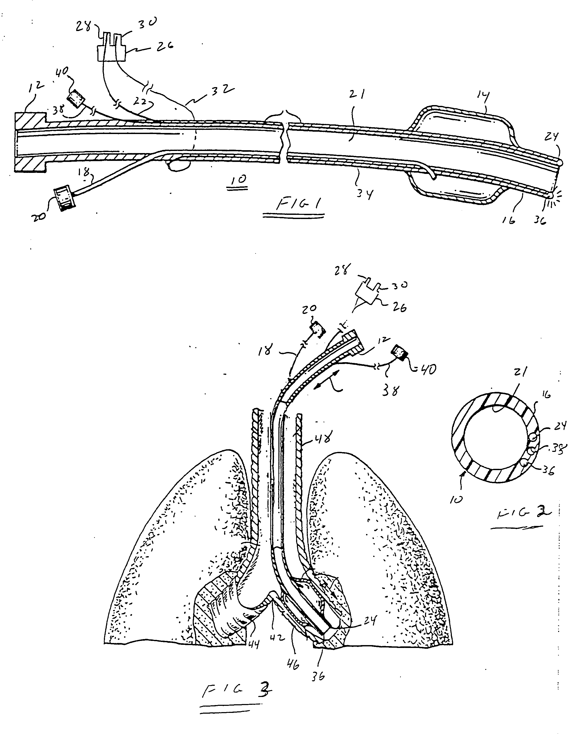
[0020] Referring to FIG. 1, there is shown an endotracheal tube 10 having a connector 12 for connection to a conventional ventilator to assist a patient's breathing function. The endotracheal tube includes an inflatable balloon 14 in proximity to its distal end 16. The inflatable balloon is inflated by a tube 18 connected through a connector 20 to a small syringe-like air pump after the endotracheal tube has been inserted into a patient's trachea.

[0021] Prior endotracheal tubes do not permit any visualization of a patient's tracheal and bronchial passages. If such visualization is needed, connector 12 is disconnected from the ventilator and a conventional bronchoscope is inserted down through hollow passage 21 of the endotracheal tube to allow a physician to determine if a lot of mucus is present in either lung or in either of the left or right stem main bronchi. If it is necessary to suction mucus out of either of the patient's lungs, a suctioning tube is inserted through hollow p...


PUM


Abstract

A low cost camera and radio frequency transmitter are coupled to an endotracheal tube to obtain an image in real time of tissue at the distal end of the endotracheal tube. The image recorded by the camera is transmitted to a low cost radio frequency receiver nearby and conveyed to a video monitor to display the image. The use of a wireless transmission system avoids the presence of wires and cords that otherwise might become entangled and cause the endotracheal tube to be inadvertently repositioned or pulled out of the patient.

Description

BACKGROUND OF THE INVENTION [0001] The present invention relaters to endotracheal tubes and, more particularly, to an endotracheal tube having an illuminator at its distal end and coupled with detachably attached camera for wireless transmission of an image to a receiver for display on a video monitor. [0002] The basic tenets attendant endotracheal tubes having an illuminator at the distal end are illustrated and described in U.S. Pat. No. 5,285,778 and relating to an invention by the present inventor; which patent is incorporated herein by reference. The endotracheal tube described therein includes an optical fiber extending through the endotracheal tube to a viewing lens at the distal end of the tube. An eye piece is attached to the proximal end of the optical fiber to permit viewing through the lens. Illumination of the area under inspection is provided by a high intensity light source extending via the endotracheal tube to an illumination port at the distal end. [0003] An endotr...

Claims


Application Information

Patent Timeline
IPC IPC(8): A61B1/05A61B1/267A61B5/00A61M16/04
CPCA61B1/00016A61B1/042A61B1/267A61M16/04A61M16/0411A61B5/0013A61M16/0434A61M16/0488A61M2205/3561
Inventor MACKIN, ROBERT A.
Owner MACKIN ROBERT A
Why Eureka
Try Eureka