Intramedullary screw and tang for orthopedic surgery

a technology which is applied in the field of intramedullary screw and tang for orthopedic surgery, can solve the problems of high cost, complex methods, and difficult retracting, and achieve the effects of simple components, easy control of steps, and reduced production costs

Inactive Publication Date: 2005-08-11
DOUBLER ROBERT L +1
View PDF13 Cites 80 Cited by
  • Summary
  • Abstract
  • Description
  • Claims
  • Application Information

AI Technical Summary

Benefits of technology

[0009] Therefore, it is an objective of this invention to teach a surgical intramedullary screw having simple components which can be quickly assembled to produce the finished product.
[0010] It is another objective of this invention to teach forming each of the components by easily controlled steps reducing production costs.

Problems solved by technology

These methods are complex and difficult to retract should the nail or lag screw assembly require extraction and do not deploy through the cortical bone.
In production, these devices require very precise tolerances, machining and assembly which results in high costs.

Method used


Image

  • Intramedullary screw and tang for orthopedic surgery
  • Intramedullary screw and tang for orthopedic surgery
  • Intramedullary screw and tang for orthopedic surgery

Examples


Embodiment Construction

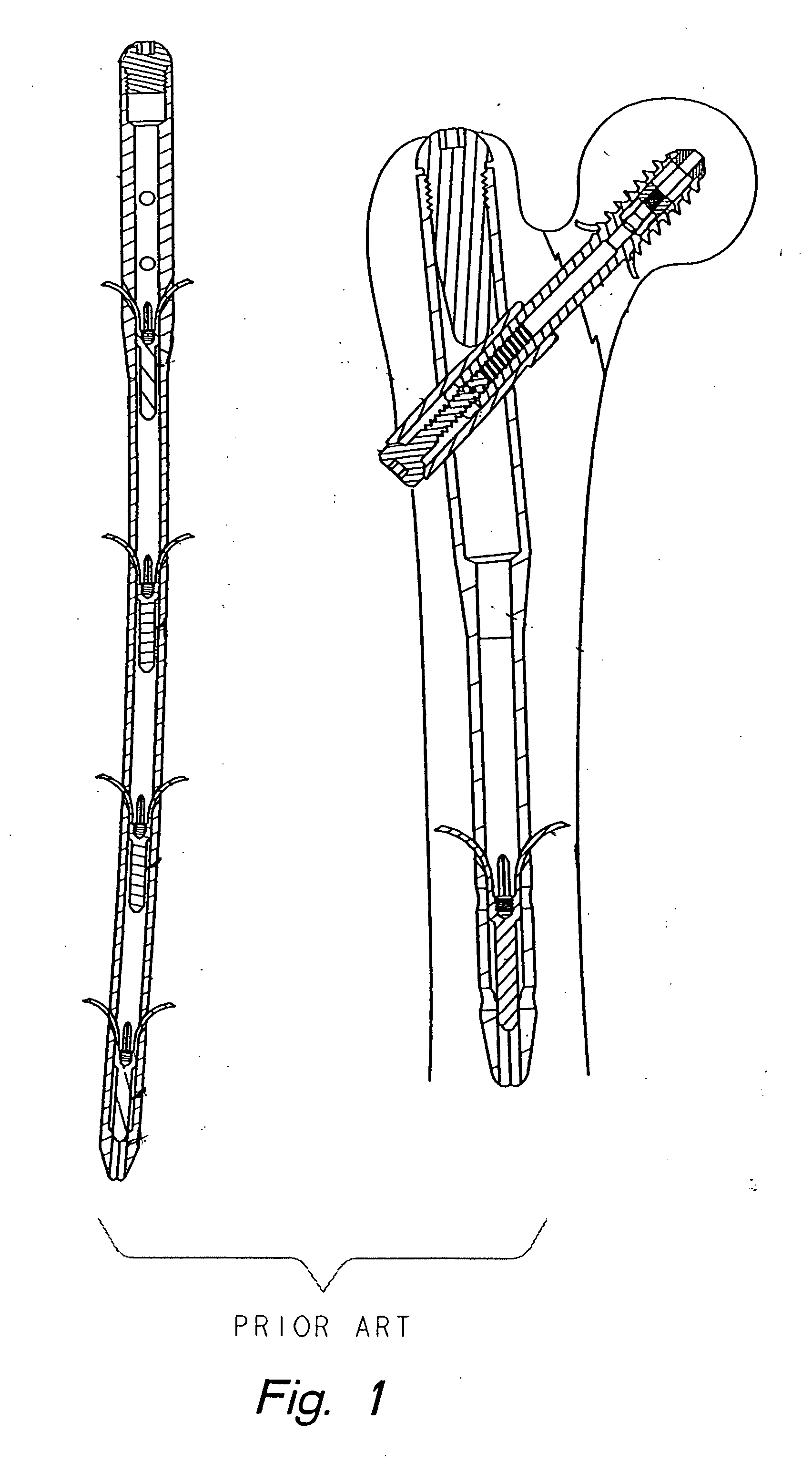
[0019] In FIG. 1, prior art intramedullary screws used for applying compression across a fracture are illustrated. The tang body is formed as a complex one piece component with a tang body and tangs which generally requires a single choice of material. To change the dimensions or the materials for the tangs, relative to the tang body, requires the component to be changed, as a whole.

[0020] The tang body has a protrusion on the leading end which acts as a guide to register the tangs with the exit holes. The tang body has a threaded blind bore for engaging a tool for deploying the tangs. The tool is threaded into the bore and then a retrograde pulling force is exerted on the tool to displace the tangs through the exit holes. This results in a force acting to dislodge the screw.

[0021] The leading end of the intramedullary screws are formed of a one piece construction with the shaft of the screw. Therefore, the tang body must be inserted through the length of the screw which requires ...


PUM


Abstract

One method of reducing fractures in long bones is to insert an intramedullary screw through the bone canal across the fracture and deploy tangs to increase the purchase of the screw. Compression is then applied along the screw to bring the broken bone together. An improved low cost lag screw has a cannulated shaft with a shaped bore in the leading end. A similarly shaped tang body is movably disposed in the leading end bore. The tang body has several tangs laser welded about the periphery and extending from the tang body. The shaped surfaces of the bore have exit holes and the ends of the tangs are adjacent the holes. An end cap is laser welded to the leading end of the shaft.

Description

FIELD OF THE INVENTION [0001] The present invention generally relates to an intramedullary system for coupling first and second bone portions across a fracture therebetween. BACKGROUND OF THE INVENTION [0002] In the 1960s, the compression hip screw was introduced, resulting in improved fixation of the proximal femur. A lag screw assembly was inserted into the femoral head, a plate was attached to the lateral femur, and a compression screw joined the two. These implants provided a more rigid structure for the patient and allowed the surgeon to compress the fractured fragments against each other thereby decreasing the time to mobility. A number of compression hip screws have been introduced for fracture fixation about the proximal femur. [0003] Newer devices and inventions explored additions to the nail and lag screw assembly to improve the fixation and ease or eliminate the need to locate the distal screw holes. These newer devices are commonly classified as “expanding devices” and e...

Claims


Application Information

Patent Timeline
Patent Type & Authority Applications(United States)
IPC IPC(8): A61B17/72A61B17/76A61B17/86
CPCA61B17/7225A61B2017/8655A61B17/8625A61B17/7266
Inventor DOUBLER, ROBERT L.HAMMILL, JOHN E.
Owner DOUBLER ROBERT L
Why Eureka
Try Eureka