Method, tool and system for increasing the efficiency of a design process

a design process and tool technology, applied in the field of methods, tools and systems for increasing the efficiency of a design process, can solve the problems of not being able to efficiently aid the design team, not easy to follow, and placing an undue burden on the design team, so as to achieve easy extraction, simple structure, and efficient and flexible

Inactive Publication Date: 2005-08-11
ROLLS ROYCE PLC
View PDF4 Cites 36 Cited by
  • Summary
  • Abstract
  • Description
  • Claims
  • Application Information

AI Technical Summary

Benefits of technology

[0035] The fact that the present invention has nodes allows a much simpler structure to be used to capture, store and retrieve information. This allows the tool to be more efficient and more flexible than previous systems, as well as allowing the information contained to be easily extracted for use on other design projects. The tool can readily be updated and adapted to a particular situation or context by users because unlike with previous systems, a user is not “boxed in” by the software.
[0036] Nodes may automatically be resized to display text of arbitrary width and number of lines. Particular types of node may be represented by a background shape or colour overlaid by text. This means that there is no longer a need ...

Problems solved by technology

However, formal recording processes that do not aid, for example, a design team in efficiently reaching a design solution have been found to place an undue burden on the design team, in terms of additional effort in formulating the required records and time away from working on the design solution in question.
Informal recording processes tend to treat records as unstructured information, and accordingly it is not easy subsequent to the recording of information to access the rationale in response to a query.
Also the informality of such an approach does not aid design teams in efficiently reaching a design solution for the current design problem.
Although successful, the aforementioned types of method and system were relatively inflexible and complex designs, which did not readily lend themselves to classification and indexing, were not always able to be incorporated in a readily accessible format or stored.
More importantly no opportunity was provided in the system disclosed in U.S. Pat. No. 5,471,560, to refer to design proposals, ideas or models that were unsuccessfully attempted.
It has been a problem ...

Method used


Image

  • Method, tool and system for increasing the efficiency of a design process
  • Method, tool and system for increasing the efficiency of a design process
  • Method, tool and system for increasing the efficiency of a design process

Examples


first embodiment

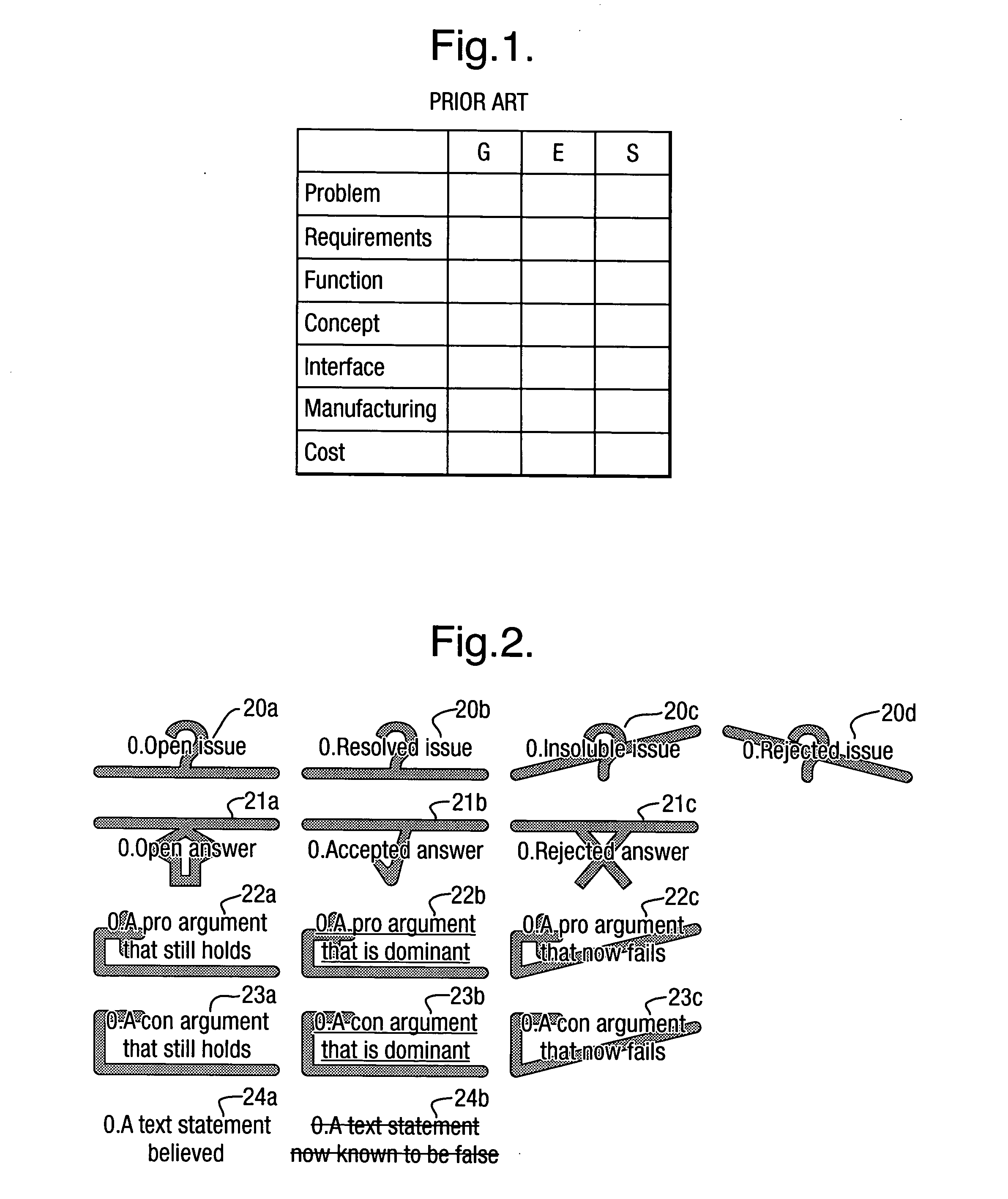
[0093] Referring to FIGS. 1 to 5 there is shown the invention which is described with reference to a particular problem encountered during a design and diagnosis project. Although reference is made to several aspects of a jet engine, only diagrammatical references are depicted in the Figures.

[0094] Previously, as depicted for example in FIG. 1, design processes and procedures comprised a process of generating, evaluating and storing solutions in a matrix or linear format. A key problem associated with this type of design process was the fact that unless a clear and consistent indexing system was used, with nomenclature universally understood by current (and future) members of a design team, there were flaws in the system. Another drawback with such liner type systems was the inability to retrieve specific pathways leading to the conclusion of a particular design and the associated reasons for making that design.

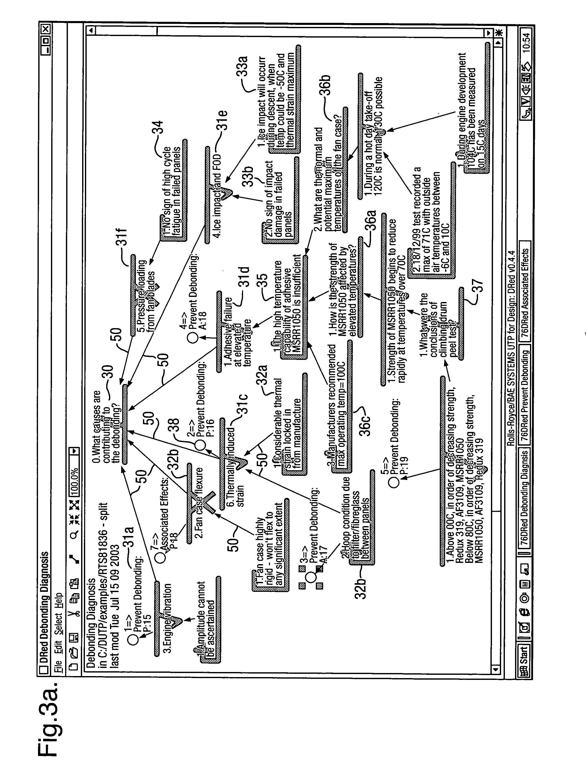
[0095] The present invention is described with specific reference to a ...

second embodiment

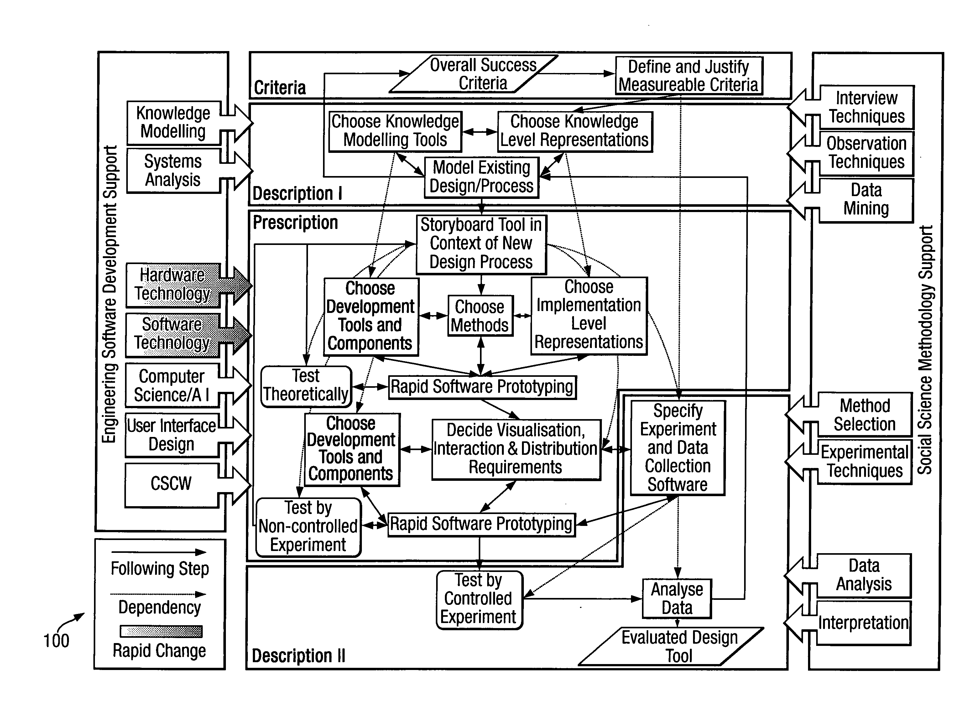
[0136] Referring now to FIGS. 6 to 10, which illustrate the invention, FIG. 6 shows a graphical representation of methodology used for designing and testing the present invention. The methodology hereindescribed is a practical approach, intended to enable development of usable software prototypes as early as possible in research. The methodology provides a choice of high level languages, tools, reusable software components, integration and code-hardening mechanisms.

[0137]FIG. 7 shows how the methodology was applied to the design and testing of the present invention, and the tasks are numbered in the order that they were performed. Task 101 is “Overall Success Criteria” and states the basis for judgement of success or failure of the project under which the invention was created. The criteria were:

[0138]“Did the project correctly identify crucial problems faced by aerospace industry designers, in the capture, sharing and reuse of knowledge?” and “Did the project suggest how one or mo...


PUM


Abstract

The invention relates to a method, tool and system for increasing the efficiency of a design process, particularly the capture and reuse of rationale behind design decisions. A tool having an interactive graph editor is used to capture a first design rationale of a first design project, the first design rationale containing data on at least one design issue and a processing means allows the first design rationale to be identified when the at least one design issue is encountered on a second design project. A computer and program are also described and these may be used as part of a system.

Description

BACKGROUND [0001] This invention relates to a method, tool and system for increasing the efficiency of a design process. In particular this invention relates to improvements in the efficiency of the capture of the rationale behind design decisions. Such captured design rationale may subsequently be reused in future design decisions which may be associated with the same or different design projects or problems. [0002] Designing complex systems or products, such as jet engines, involves many specialists working together as a large interdisciplinary team. Each design decision is influenced by many complex factors to achieve an optimal solution. For example, during development of a particular jet engine problems may be experienced which makes it impossible to routinely keep within required tolerances when assembling engine components once the components are removed from tooling jigs. This may be due to one of several issues or more, and is usually a combination of such issues. [0003] So...

Claims


Application Information

Patent Timeline
IPC IPC(8): G06F17/50G06N5/00
CPCG06F17/50G06F30/00
Inventor BRACEWELL, ROBERT H
Owner ROLLS ROYCE PLC
Why Eureka
Try Eureka