
Self-winding generator

a self-winding generator and generator technology, applied in the direction of electric generator control, couplings, fluid couplings, etc., can solve the problem that hydroelectric power plants cannot afford luxury

Inactive Publication Date: 2005-08-18
FIELDER WILLIAM SHERIDAN
View PDF6 Cites 2 Cited by
  • Summary
  • Abstract
  • Description
  • Claims
  • Application Information

AI Technical Summary

Problems solved by technology

This luxury is not available to hydroelectric power plants that rely on the oceans' currents, tides and waves, or to wind-driven turbines.

Method used


Image

  • Self-winding generator
  • Self-winding generator
  • Self-winding generator

Examples


embodiment

—PREFERRED EMBODIMENT FIG. 4

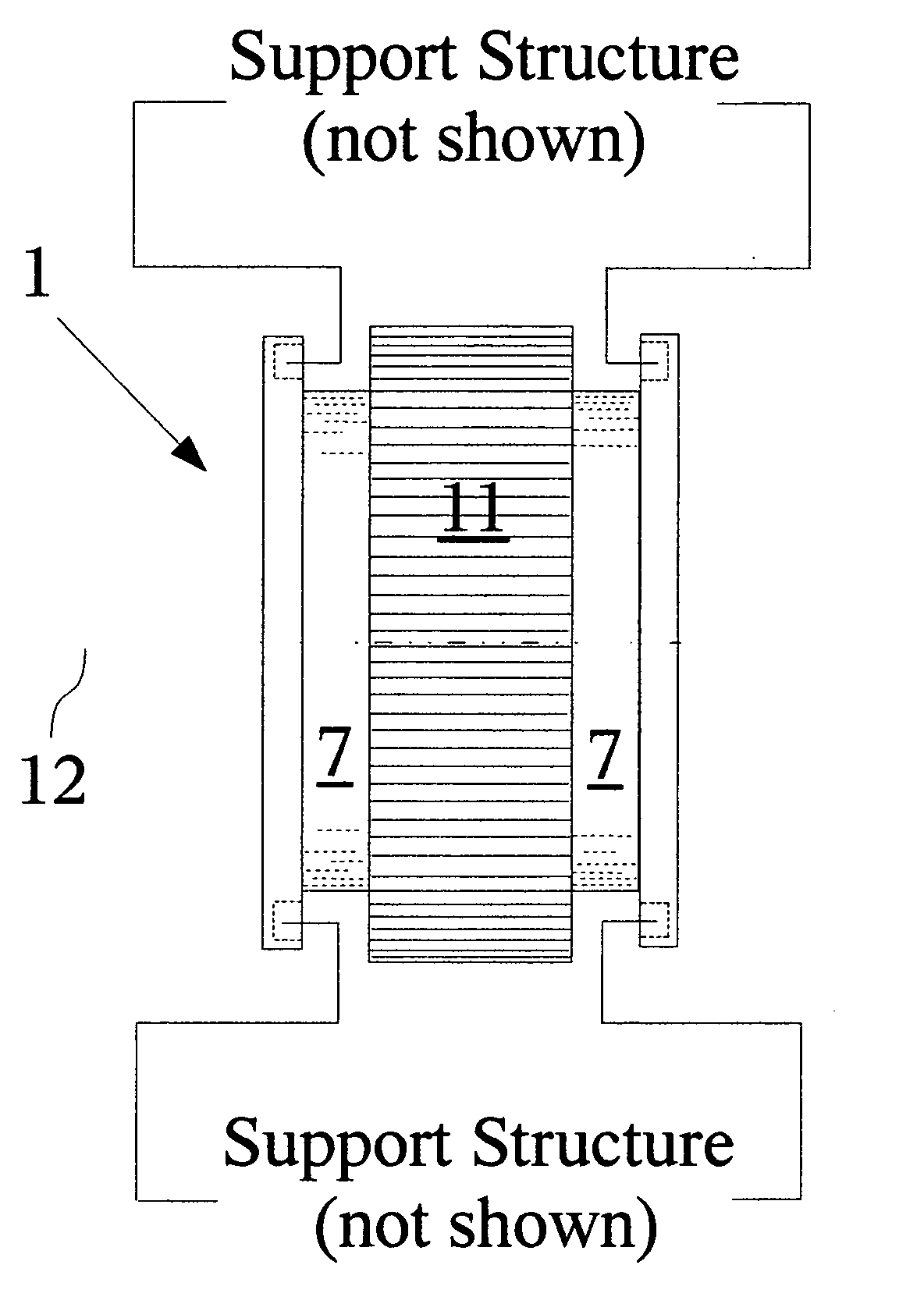
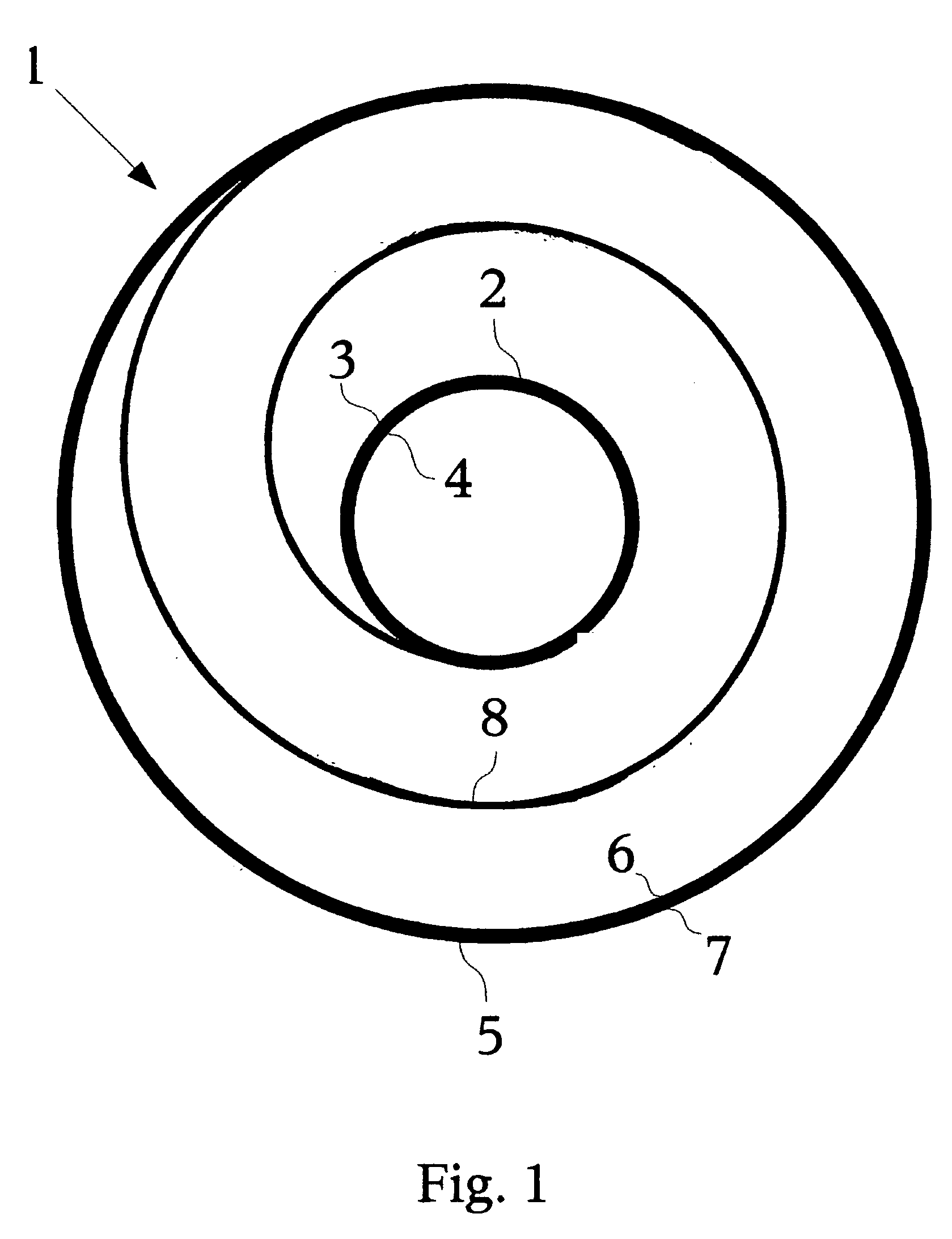
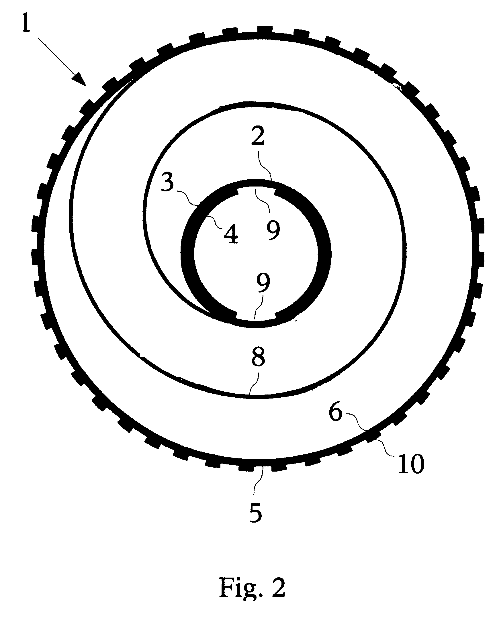
[0044] The Self-Winding Generator includes: an energy capture system 23; an energy storage spring 1, equivalent to a watch's mainspring, and support structure and bearings (not shown); an electric generator (not shown); and optional gear boxes / turbines (not shown).

[0045] The energy capture system (E.C.S.) 23 is independent of the Self-Winding Generator; therefore the specific type or E.C.S. 23, hydraulic or pneumatic, is irrelevant so long as a means of engagement 16 is possible.

[0046] An optional gear box / transmission (not shown) positioned between the said energy capture system 23 and the outer surface 7 of energy storage spring 1 will allow for the independent operation. Another optional gear box / transmission (not shown) aligned between the energy storage spring (E.S.S.) 1 and the electric generator (not shown) will allow the E.S.S. 1, or multiple E.S.S.s 1 to store rotational energy to capacity before transferring that energy to the electric generat...


PUM


Abstract

An uninterruptible rotational energy supply calibrated to provide constant rotational energy to electric generators and other apparatus in environments where fluctuations in kinetic energy are found. Such environments include the pause between the ebb and flow of the oceans' tides and waves as well as variations in the velocity of the oceans' currents. Wind-driven turbines may also be another beneficiary of this technology.

Description

CROSS-REFERENCE TO RELATED APPLICATIONS: [0001] This application claims the benefit of provisional patent application Ser. No. 60 / 545306, filed Feb. 17, 2004 by the present inventor.FEDERALLY SPONSORED RESEARCH [0002] Not applicable. SEQUENCE LISTING OR PROGRAM [0003] Not applicable. BACKGROUND OF INVENTION [0004] 1. Field of Invention [0005] This invention relates to energy capture systems, typically hydraulic turbines that capture the inconsistent kinetic energy found in the oceans' currents, tides, and waves, as well as wind turbines in need of a more regulated uninterrupted supply of rotational energy. [0006] 2. Prior Art [0007] Previously energy capture systems that relied on inconstant sources of kinetic energy, such as wind turbines, had to make do. The only mechanism available to even out such inconstancies was found in self-winding watches. These mechanisms capture the kinetic energy of a swinging arm via a pendulum and store that energy in the watch's mainspring. The mains...

Claims


Application Information

Patent Timeline
Patent Type & Authority Applications(United States)
IPC IPC(8): F03G7/10F16D31/02
CPCY02E10/38F03G7/10Y02E10/30
Inventor FIELDER, WILLIAM SHERIDAN
Owner FIELDER WILLIAM SHERIDAN
Learn More