Long-span lead screw assembly with anti-backlash nut

a long-span lead screw and anti-backlash technology, which is applied in mechanical equipment, gearing, hoisting equipment, etc., can solve the problems of excessive whipping and vibration force, limited operation of any lead screw device, and unstable screw rotation within the reinforcing rail. , to achieve the effect of safe operation at high speed and minimizing whipping and vibration of the lead screw

Active Publication Date: 2005-08-18
KERK MOTION PROD
View PDF24 Cites 17 Cited by
  • Summary
  • Abstract
  • Description
  • Claims
  • Application Information

AI Technical Summary

Benefits of technology

[0003] In one aspect, the present invention relates to a lead screw assembly which comprises a lead screw rotatable about a central axis and a reinforcing rail having a hollow tubular portion surrounding the lead screw and a slot extending lengthwise of the central axis. The lead screw includes plurality of first threaded portions having an outer diameter and extending lengthwise of the lead screw; and at least one second gap portion having an outer diameter that is less than the outer diameter of the first threaded portions. The second gap portion is positioned be

Problems solved by technology

However, the operation of any lead screw device is limited by the “critical speed” of the screw shaft.
Beyond a certain critical speed, the rotation of the screw within the reinforcing rail becomes unstable.
Beyond this spe

Method used


Image

  • Long-span lead screw assembly with anti-backlash nut
  • Long-span lead screw assembly with anti-backlash nut
  • Long-span lead screw assembly with anti-backlash nut

Examples


Embodiment Construction

[0020] A description of preferred embodiments of the invention follows.

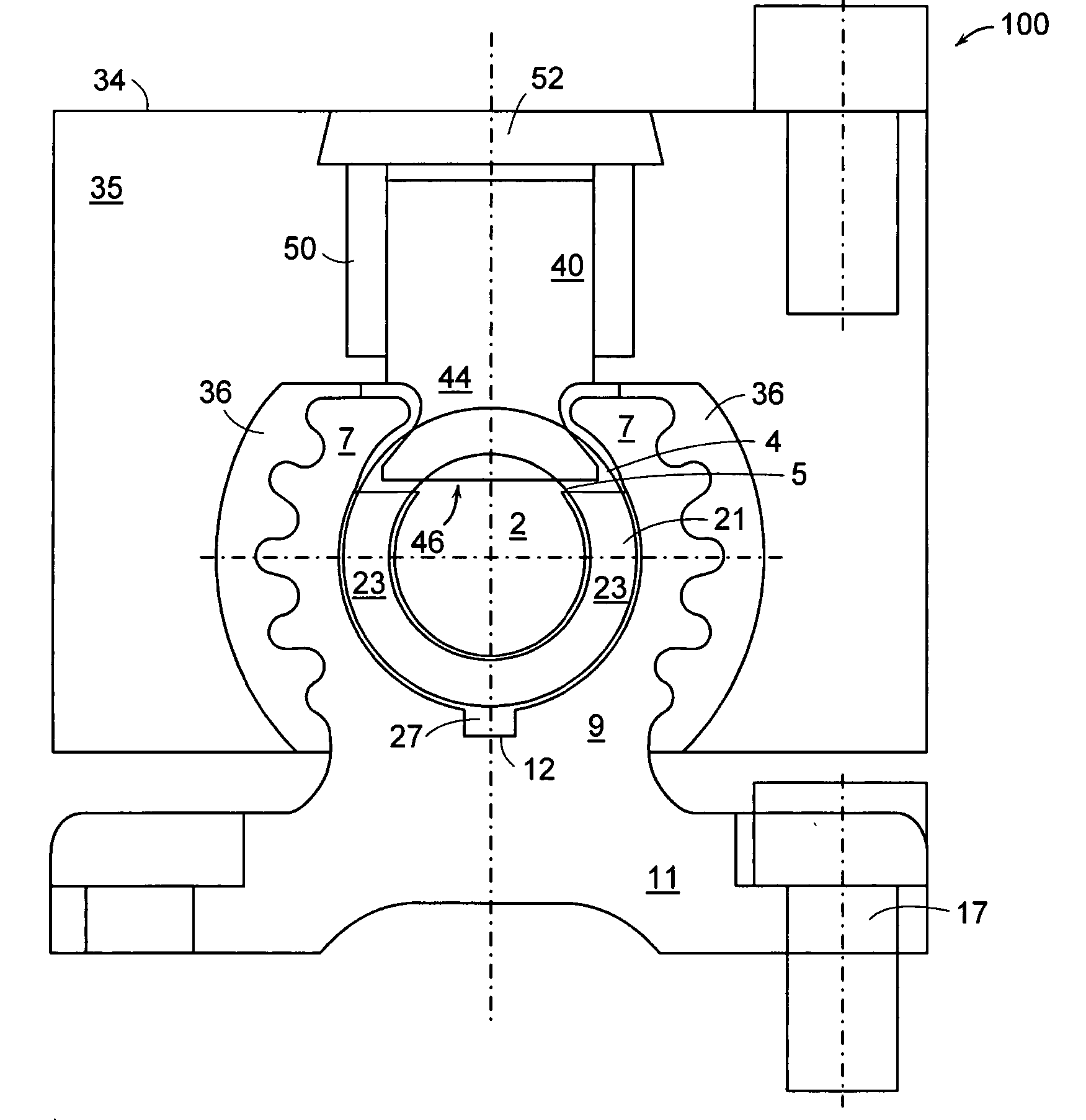
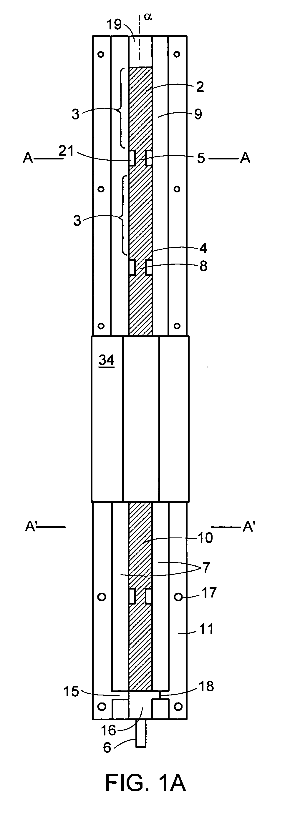
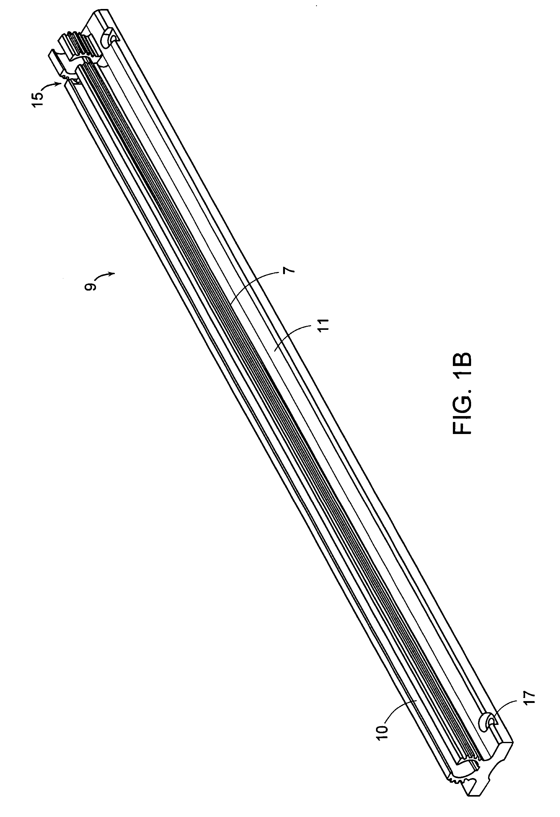
[0021] A reinforced lead screw assembly 100 according to one embodiment of the invention is seen assembled in plan view in FIG. 1A. A section of the assembly 100 between A-A and A′-A′ is shown in perspective view in FIG. 2. The lead screw assembly 100 includes a lead screw 2 that is rotatable about an axis, α. A projection 6 is formed on one end of the lead screw 2 to connect it to a reversible driving motor (not shown) in order to rotate the lead screw 2 alternatively in clockwise and counterclockwise direction. The lead screw 2 can be made from any suitable material, such as steel. The screw could also be aluminum, for example.

[0022] The screw 2 includes a plurality of first threaded portions 3 which run along the length of the screw. The threaded portions 3 include threads 4 having a first diameter. Between each of the first threaded portions 3 are second gap portions 5. The gap portions 5 preferably include...


PUM


Abstract

A lead screw assembly having a lead screw rotatable within a hollow tubular portion of a reinforcing rail. A nut engages with threads of the lead screw and is movable along the reinforcing rail. The lead screw includes plurality of first threaded portions having an outer diameter and extending lengthwise of the lead screw; and at least one second gap portion having an outer diameter that is less than the outer diameter of the first threaded portions. The second gap portion is positioned between adjacent first threaded portions of the lead screw. At least one generally U-shaped bearing is secured within the reinforcing rail and contacts the lead screw at a second gap portion. Each U-shaped bearing supports the lead screw along its length as the screw rotates within the rail, so that the lead screw assembly can be safely operated at high speeds over comparatively long distances while minimizing whipping and vibration of the lead screw. The reinforcing rail can include a base portion which permits the assembly to be securely mounted to a support structure at any convenient location along its length. An anti-backlash nut assembly includes a threaded follower for engagement with the threads of a lead screw. A pair of wedges bias the follower in a radial direction so that the threads of the follower are brought into forcible engagement with the mating threads of the screw. In a preferred embodiment, the nut assembly is adjustable to provide variable levels of backlash resistance and wear-compensation.

Description

BACKGROUND OF THE INVENTION [0001] Devices and methods for bilateral motion of a load are known which utilize a rotating lead screw and a threaded nut that is driven by the lead screw. In U.S. Pat. No. 6,422,101, issued Jul. 23, 2002 to the present inventors, the entire teachings of which are incorporated herein by reference, a lead screw assembly is described which employs an anti-backlash nut assembly on a rotating lead screw. A hollow, elongated reinforcing rail extends lengthwise of and surrounds the lead screw. The reinforcing rail has a slot extending lengthwise of the central axis of the lead screw. The anti-backlash nut assembly has a nut which completely surrounds the outer diameter of the reinforcing rail, and is movable along the length of the reinforcing rail. The anti-backlash nut has a pair of threaded tongue portions which extend radially through the slot to engage the threads of the lead screw for moving the nut in reciprocating motion lengthwise of the rail. A load ...

Claims


Application Information

Patent Timeline
IPC IPC(8): F16H3/06F16H25/24
CPCF16H25/2409F16H2025/2034F16H2025/204Y10T74/19902Y10T74/19707Y10T74/18728Y10T74/19702
Inventor ERIKSON, KEITH W.ERIKSON, KENNETH W.
Owner KERK MOTION PROD
Why Eureka
Try Eureka