Photovoltaic system and method of making same

a photovoltaic system and photovoltaic technology, applied in the field of photovoltaic systems and methods of making same, can solve the problems of large solar energy collection areas, difficult mounting of photovoltaic devices to roof structures, and low efficiency of photovoltaic cells

Inactive Publication Date: 2005-08-18
OPEN ENERGY CORP
View PDF55 Cites 176 Cited by
  • Summary
  • Abstract
  • Description
  • Claims
  • Application Information

AI Technical Summary

Benefits of technology

[0012] According to a broad aspect of an embodiment of the present invention, there is provided a photovoltaic system which includes: a base, flexible membrane layer; a photovoltaic layer having at least one photovoltaic cell associated therewith; a semi-rigid layer for supporting the photovoltaic layer and imparting rigidity thereto; and a top, transparent, protective layer for protecting the base,

Problems solved by technology

Given that traditionally the efficiency of the photovoltaic cells has been relatively low, fairly large solar energy collection areas have been required to generate usable amounts of power.
There were however, certain difficulties in mounting the photovoltaic devices to the roof structures.
However, this solution tends to be expensive.
Installation tends to be time-consuming, requiring special installation techniques and hardware.
In addition, these support structures tend to be heavy and the building structures must be reinforced to accommodate their use.
Additionally, these structures tend to require extensive maintenance to keep the photovoltaic devices operational.
The foregoing disadvantages tended to discourage the broad application of roof-mounted photovoltaic systems for residential or commercial buildings.
However, where relati

Method used


Image

  • Photovoltaic system and method of making same
  • Photovoltaic system and method of making same
  • Photovoltaic system and method of making same

Examples


Embodiment Construction

[0024] The description which follows, and the embodiments described therein are provided by way of illustration of an example, or examples of particular embodiments of principles and aspects of the present invention. These examples are provided for the purposes of explanation and not of limitation, of those principles of the invention. More specifically, in the description that follows an exemplary application of a photovoltaic system in the field of roofing is described. It will however be appreciated that the present invention is not limited to photovoltaic systems for use in roofing applications. It is contemplated that the photovoltaic system described herein below may be advantageously employed in a broad range of applications and may be installed onto any surface exposed to sufficient amounts of sunlight.

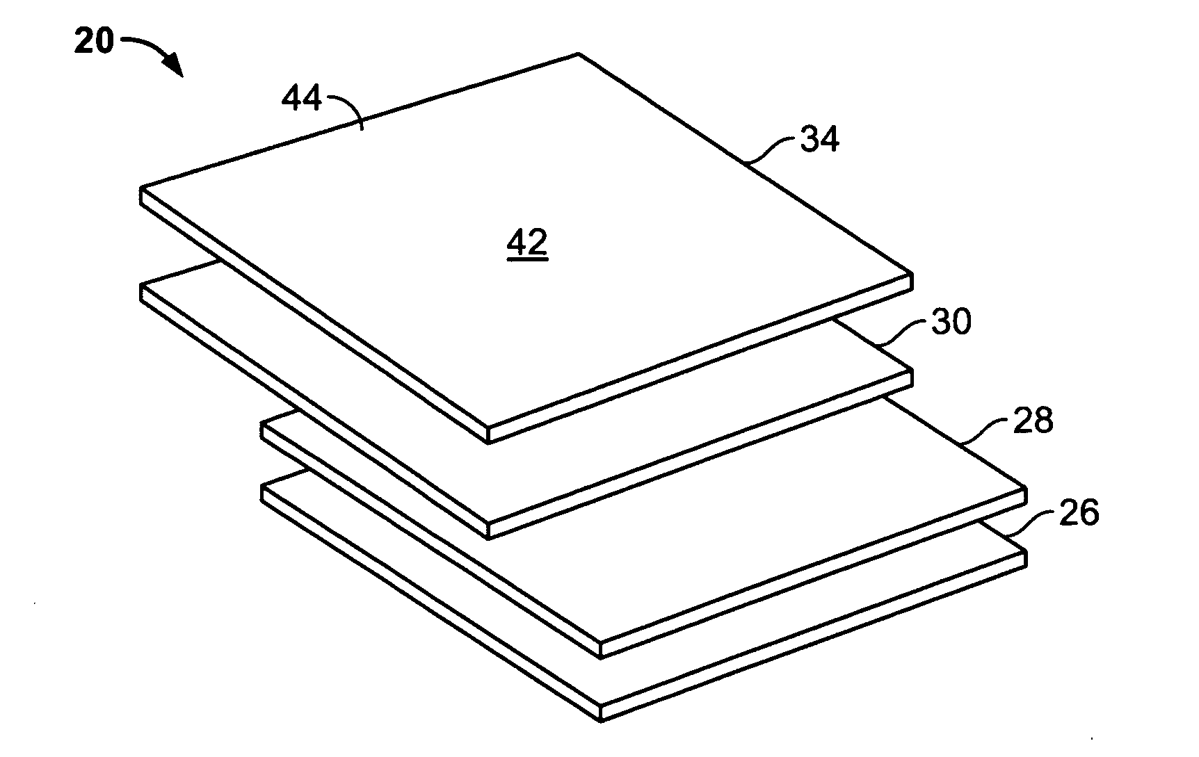
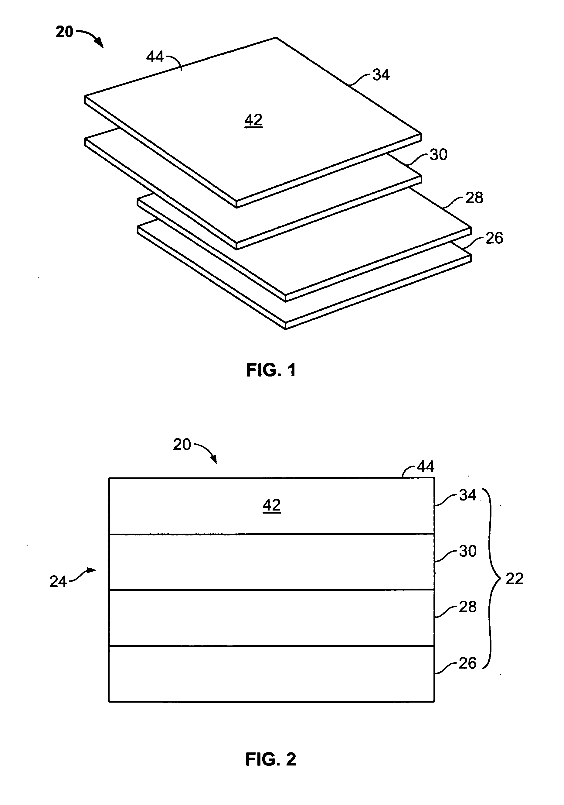
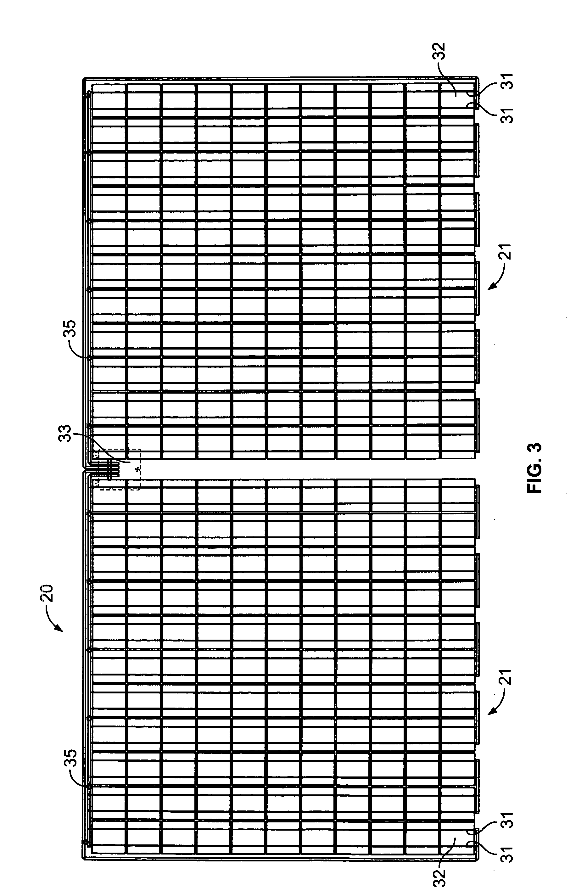
[0025] Referring to FIGS. 1, 2 and 3, there is shown a photovoltaic system designated generally with reference numeral 20. The photovoltaic system 20 is adapted for mounting ...


PUM

PropertyMeasurementUnit
Lengthaaaaaaaaaa
Lengthaaaaaaaaaa
Thicknessaaaaaaaaaa

Abstract

The present invention relates to a photovoltaic system and methods of making same. The photovoltaic system has a plurality of layers attached to each other to form a unitary structure. More specifically, the photovoltaic system includes: a base, flexible membrane layer; a photovoltaic layer having at least one photovoltaic cell associated therewith; a semi-rigid layer for supporting the photovoltaic layer and imparting rigidity thereto; and a top, transparent, protective layer for protecting the base, flexible membrane layer, the semi-rigid layer and the photovoltaic layer from exposure to the environment. The photovoltaic layer and the semi-rigid layer are disposed between the base, flexible membrane layer and the top, protective layer. Additional layers of adhesive may be disposed between the various layers to facilitate bonding thereof.

Description

RELATED APPLICATION [0001] This application claims priority to U.S. Provisional Patent Application Ser. No. 60 / 544,497, filed Feb. 17, 2004, entitled “PHOTOVOLTAIC CELL ROOFING SYSTEM”, the disclosure of which is hereby incorporated by reference. [0002] 1. Field of the Invention [0003] The present invention relates to a photovoltaic system and methods of making same. [0004] 2. Background of the Invention [0005] The increasing concern for depletion of non-renewable fossil fuels and environmental issues, and the ever-growing demand for cleaner, more cost-effective sources of energy, have spurred interest in solar power technology and applications thereof. [0006] Various photovoltaic devices having a plurality of semiconductor cells, have been developed which transform light into direct current (dc) electricity. As the electrical power generated by a photovoltaic device is proportional to the light incident on its cells, it has been necessary to install photovoltaic devices in highly i...

Claims


Application Information

Patent Timeline
IPC IPC(8): H01L25/00H01L31/042H01L31/18
CPCB32B37/0046H01L31/0504B32B37/1207B32B38/004B32B2305/08B32B2307/584B32B2307/754B32B2309/02B32B2309/027B32B2309/04B32B2309/10B32B2315/08B32B2327/12B32B2419/06B32B2457/12H01L31/02021H01L31/048Y02B10/12Y02E10/50H02S40/36H01L31/044H02S20/23B32B37/1018Y02B10/10
Inventor LAALY, HESHMAT OLLAHLEVY, STANLEY BURTONCHANEY, JAMES ANTON
Owner OPEN ENERGY CORP
Why Eureka
Try Eureka