Elevator

a technology of elevators and elevators, applied in the field of elevators, can solve the problems of not being able to observe the standard for elevator installation in the country in question

Inactive Publication Date: 2005-08-18
TOSHIBA ELEVATOR KK
View PDF3 Cites 8 Cited by
  • Summary
  • Abstract
  • Description
  • Claims
  • Application Information

AI Technical Summary

Benefits of technology

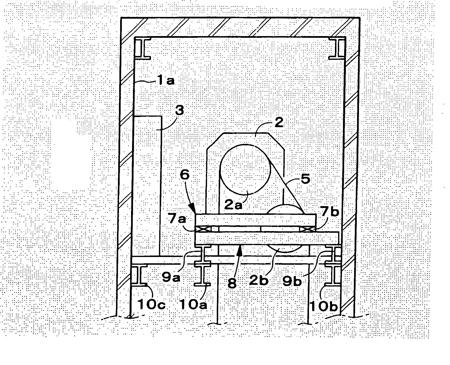
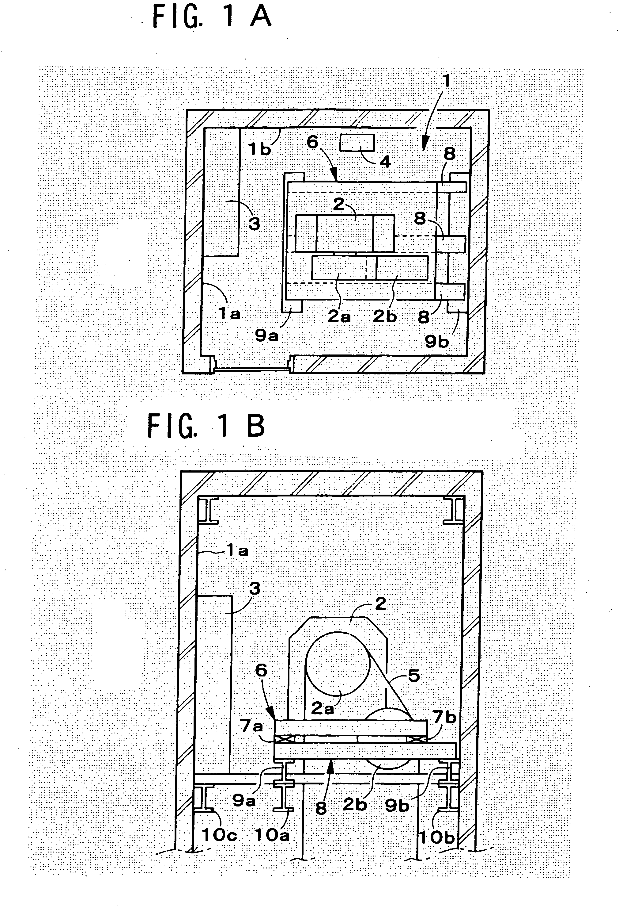
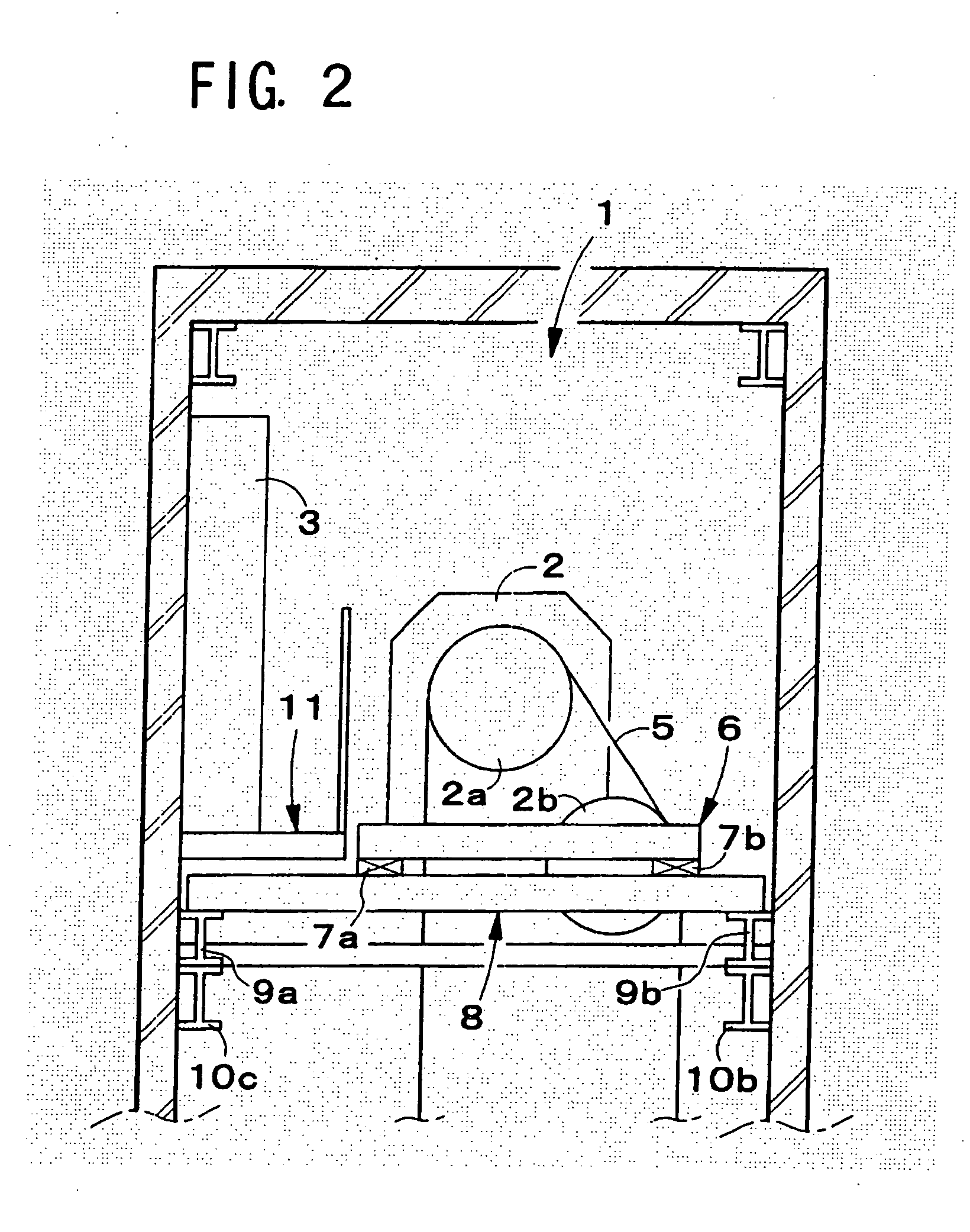
[0053] Specifically, in an elevator according to the present invention, the pair of left and right cage-side sheaves can be fully separated as far as possible in the left / right direction, so the interval in the left / right direction between the traction sheave and the cage-side stop portion in the interior of the machinery chamber can be made wider, making it possible to obtain a large workspace in the interior of the machinery chamber.
[0056] In this way, since the angle of winding-on of the wire rope with respect to the traction sheave can be made 180° or more, reliable transmission of the pulling-up force to the wire rope from the traction sheave can be achieved by ensuring fully satisfactory traction performance.
[0058] Specifically, if a small diameter rope of external diameter for example 4 to 6 mm is adopted as the wire rope, the external diameter of the cage-side sheave and the traction sheave can be kept small, making it possible to increase the degree of freedom of arrangement of the sheaves.
[0060] In this way, the space in the left / right direction occupied by the drive device in the interior of the machinery chamber can be reduced, so the workspace in the interior of the machinery chamber can be increased in the left / right direction.

Problems solved by technology

However, as explained above, this made it impossible to observe the standard for elevator installation of the country in question.

Method used


Image

  • Elevator
  • Elevator
  • Elevator

Examples


first embodiment

[0078] First of all, the overall construction of an elevator according to a first embodiment will be described with reference to FIG. 3 and FIG. 4. The cage 20 descends / descends within an elevator shaft S provided in a building, guided by a pair of left and right cage-side guide rails 21L, 21R.

[0079] A pair of left and right doors 22 L, 22 R provided in the front face of the cage 20 open and close in the left / right direction.

[0080] A cage frame that supports the cage 20 comprises an upper beam 23 that extends horizontally in the left / right direction at the top of the cage 20 and a sheave support beam 24 that extends with its upper surface connected with the upper beam 23 and inclined forward / rearwards and left / right in the horizontal plane with respect to the upper beam 23 so as to tightly adhere to the undersurface of the upper beam 23 in the middle thereof in its longitudinal direction.

[0081] Also, a pair of left and right cage-side sheaves 25L, 25R are respectively freely rota...

second embodiment

[0112] Next, an elevator 200 according to a second embodiment will be described with reference to FIG. 10 to FIG. 14.

[0113] In the elevator 100 according to the first embodiment described above, the cage-side stop portion 44 was supported by the supporting frame 60 provided on the floor 31 of the machinery chamber 30.

[0114] However, for example in cases where sufficient strength of the floor 31 of the machinery chamber 30 cannot be guaranteed or in cases where the cage 20 is of large size and heavy, the cage-side stop portion 44 cannot be directly supported by the floor 31 of the machinery chamber 30.

[0115] In such cases, as shown in FIG. 10 and FIG. 11, the cage-side stop portion 44 may be supported by a support beam 61 comprising a pair of left and right C-section (C-shaped) steel members 61a, 61b extending fully in the forwards / rearwards direction within the machinery chamber 30.

[0116] Furthermore, the pair of front and rear level-raising supporting beams 62, 63 are fixed, pl...


PUM


Abstract

A drive device (42), a traction sheave (41) and a weight-side stop portion (46) are arranged above one (21L) of a pair of left and right cage-side guide rails and a cage-side stop portion (44) and speed governor (47) are arranged above the other (21R) cage-side guide rail. Also a wide workspace can be guaranteed in the middle of the floor (31) of the machinery chamber (30), since the control panel (48) is arranged along the middle of the inside wall surface (37) of the front face of the machinery chamber (30). Furthermore, provision of an additional supporting beam mounted in the building is unnecessary, since the machine beam (53) can extend fully in the forwards / rearwards direction in the interior of the machinery chamber (30).

Description

TECHNICAL FIELD [0001] The present invention relates to an elevator and more particularly relates to an elevator provided with a machinery chamber (sometimes this is called a machine room) which is of equivalent area to the horizontal cross-section of the elevator shaft (elevator hoistway or ascending / descending path, sometimes simply called the shaft) yet in which the working space necessary for maintenance and inspection of the hoisting machine or control panel and speed governor (sometimes simply called governor) and the like can be enlarged, and wherein there is no need to add a supporting beam in the building in order to install the hoisting machine. TECHNICAL BACKGROUND [0002] Conventionally, as disclosed in Laid-open Japanese Patent Publication No. H. 8-175776 (FIG. 6 and FIG. 7), a machinery chamber is provided above the elevator shaft whereby the elevator cage (cage) and / or counterweight (balancing weight) and the like ascend and descend and the hoisting machine and / or cont...

Claims


Application Information

Patent Timeline
Patent Type & Authority Applications(United States)
IPC IPC(8): B66B5/00B66B11/00
CPCB66B11/004B66B11/0015B66B11/04
Inventor KAWASAKI, KANASAMI, IKUOISHII, TAKASHIMIYAKOSHI, KAZUAKIKURAMITSU, MASAHIROIZUMI, KAZUHIROSANO, HIROSHITAKAISHI, SHIGERUFUJIMURA, SHUNURATA, TAKANORITAKASAWA, SATOSHIHIGASHI, MASAYUKI
Owner TOSHIBA ELEVATOR KK
Why Eureka
Try Eureka