Clamping jig for tube connection

a technology of clamping jigs and tubes, which is applied in the field of clamping jigs, can solve the problems of increasing the size of the clamping jig, user's fingers may not be able to hold the gripping portions and apply a sufficient gripping force, and the inability to open the gripping portions, etc., to achieve the effect of suppressing relative variation of angle, increasing distance between the effort point and the fulcrum point, and increasing the distance between the effor

Active Publication Date: 2019-10-24
YODOGAWA HI TECH CO LTD +1
View PDF0 Cites 1 Cited by
  • Summary
  • Abstract
  • Description
  • Claims
  • Application Information

AI Technical Summary

Benefits of technology

[0008]Furthermore, the clamping jig has a configuration in which the gripping portions that serve as the effort point are provided on the base end side, and the clamping portions that serve as the load point are provided on the leading end side, with the cross-supported portion serving as the fulcrum point. Accordingly, in order to provide a large clamping force with a small gripping force, it is necessary to have a long distance between the effort point and the fulcrum point and a short distance between the fulcrum point and the load point. However, increasing the distance between the effort point and the fulcrum point results in an increase in the size of the clamping jig. On the other hand, reducing the distance between the load point and the fulcrum point so as to make the clamping jig compact requires that the gripping portions are opened over a large range in order to open the clamping portions. Also, a large workspace is required, and the ease of operation decreases.
[0009]It is an object of the present invention to provide a clamping jig for tube connection, with which it is possible to clamp tubes even in a small and narrow space. It is another object of the present invention to provide a clamping jig for tube connection that can provide a large clamping force while being compact.
[0020]With the clamping jig for tube connection according to the present invention, the pivoting portion that serves as the fulcrum point is provided on the base end side and the clamping portions that serve as the load point are provided on the leading end side, and thus the distance between the fulcrum point and the load point can be increased. Accordingly, it is possible to suppress relative variation of the angle between the first member and the second member when opening the clamping portions.
[0021]Also, the pressing portion that serves as the effort point on the second member is provided between the pivoting portion that serves as the fulcrum point and the clamping portions that serve as the load point, and thus the clamping jig can be made compact. Furthermore, by providing the pressing portion at a position toward the clamping portions, the distance between the effort point and the fulcrum point can be increased, and it is therefore possible to provide a large clamping force.
[0022]With respect to the first member, the first gripping portion is provided at a position recessed from the first clamping portion. Accordingly, even in the case where the distance to another tube, a device, a wall surface, or the like is short, the user can easily place his / her fingers on the first gripping portion, and thus the workability can be improved.

Problems solved by technology

However, in the case where sufficient workspace cannot be secured, or the tubes are positioned near another tube, a device, a wall surface, or the like, it may not be possible to open the gripping portions, or the user may not be able to place his / her fingers to hold the gripping portions and apply a sufficient gripping force.
However, increasing the distance between the effort point and the fulcrum point results in an increase in the size of the clamping jig.
Also, a large workspace is required, and the ease of operation decreases.

Method used


Image

  • Clamping jig for tube connection
  • Clamping jig for tube connection
  • Clamping jig for tube connection

Examples


Embodiment Construction

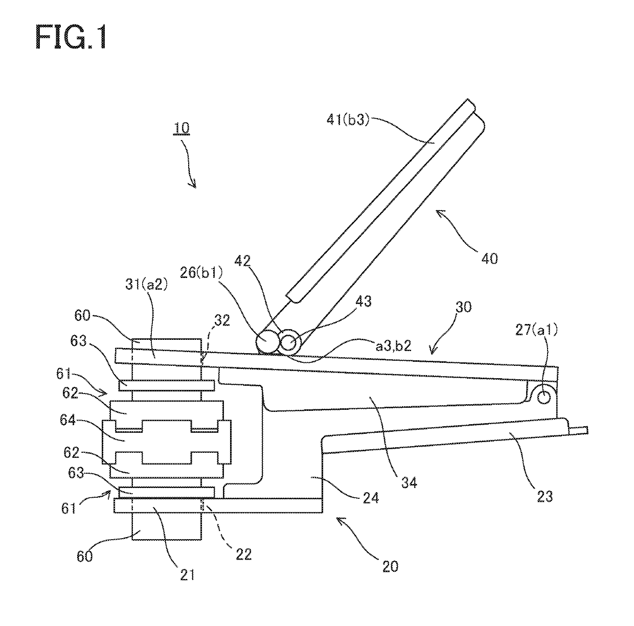
[0028]Hereinafter, a clamping jig for tube connection 10 according to an embodiment of the present invention will be described with reference to the drawings. For the sake of understanding the description, in FIG. 1, the right side will be referred to as “base end”, and the left side will be referred to as “leading end”. Also, the upper side will be referred to as “up”, and the lower side will be referred to as “down”.

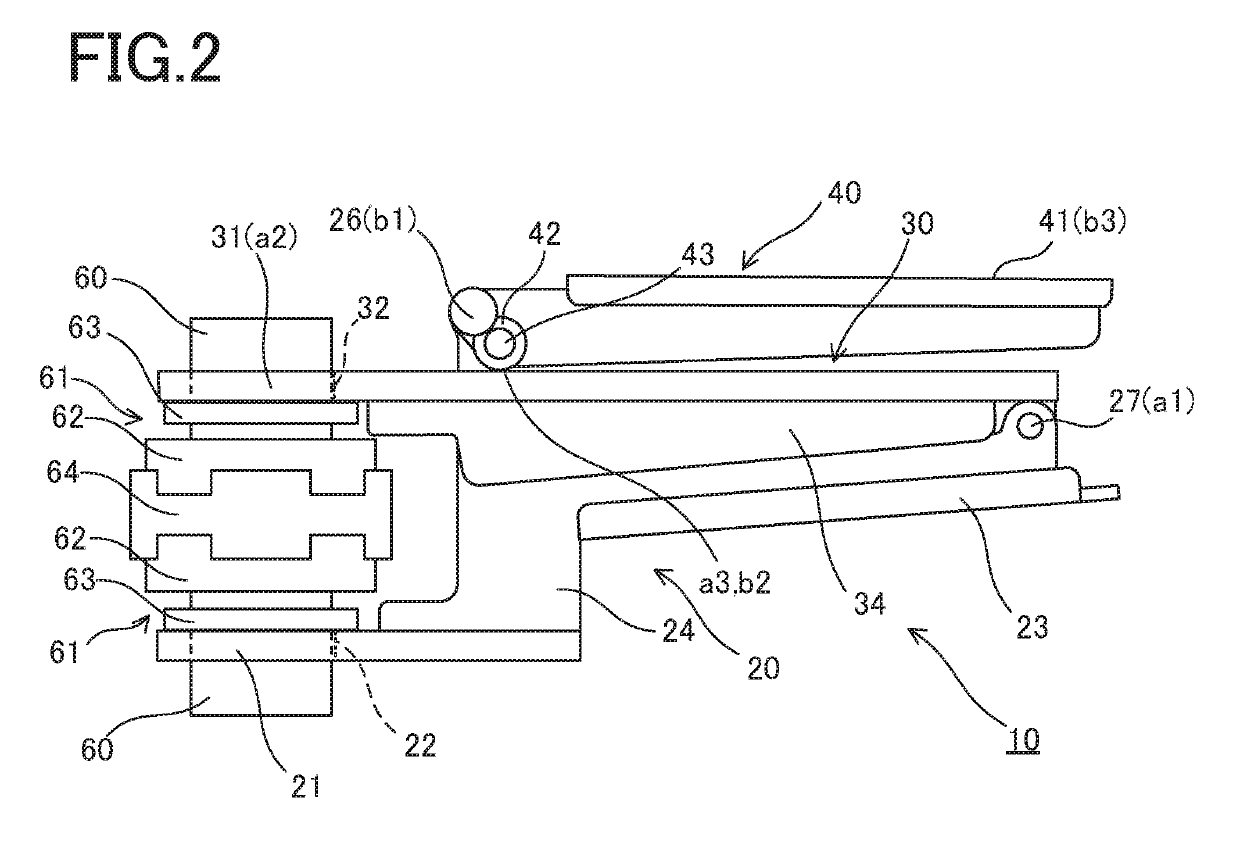
[0029]As shown in FIGS. 1 and 2, the clamping jig for tube connection 10 according to the present invention is a jig used to connect joint-equipped tubes 60 and 60. As shown in the diagrams, each tube 60 includes a joint 61 that includes a flange 62 at its leading end and a protruding annular collar portion 63 at a position behind the flange 62. The tubes 60 and 60 are connected by placing the tubes 60 and 60 facing each other with an annular sealing member 64 interposed between the flanges 62 and 62, and pressing the tubes 60 and 60 using the clamping jig 10 so as to ...


PUM

PropertyMeasurementUnit
angleaaaaaaaaaa
clamping forceaaaaaaaaaa
gripping forceaaaaaaaaaa

Abstract

The present invention provides a clamping jig for tube connection with which it is possible to clamp tubes even in a small and narrow space. A clamping jig for tube connection 10 according to the present invention is a clamping jig for tube connection that clamps joint-equipped tubes 60, each tube including a protruding collar portion 63 at a position rearward of its leading end. The clamping jig for tube connection includes: a first member 20 that includes a first clamping portion 21 that is provided at a leading end thereof and to which one of the tubes is fitted, and a first gripping portion 23 formed at a base end thereof, a second member 30 that includes a second clamping portion 31 that is provided at a leading end thereof and to which the other tube is fitted, and a base end thereof being pivotally supported at the base end of the first member by a pivoting portion 27; a support rod 25 that extends from the first member through the second member; and a lever member 40 in which a leading end thereof is pivotally supported by a support portion 26 provided in the support rod, and a lever gripping portion 41 is formed at a base end thereof, the lever member 40 enabling swinging of the lever gripping portion in a direction of the base end of the second member, and the lever member 40 including a pressing portion 42 that presses the second member on the base end side relative to the support portion.

Description

BACKGROUND OF THE INVENTIONField of the Invention[0001]The present invention relates to a clamping jig that is used to connect tubes through which a fluid flows.Description of Related Art[0002]In various types of apparatuses, such as production apparatuses, cleaning apparatuses, and assembling apparatuses, used in the field of electronics such as semiconductors, the pharmaceutical field, the biotechnology field, and other fields, tubes made of fluorinated resin are used to supply and transfer a raw material fluid, a cleaning fluid, a fuel fluid, or the like.[0003]As the tubes, joint-equipped tubes that have joints at their leading ends have been proposed. The leading ends of the joint-equipped tubes are connected via an annular sealing member, and are kept in a connected state by a clip that sandwiches the joints from the outer circumferential surface thereof (see, for example, Patent Document 1).[0004]Each joint includes an annular collar portion on the rear side thereof. When conn...

Claims


Application Information

Patent Timeline
Patent Type & Authority Applications(United States)
IPC IPC(8): B25B27/10F16L23/036
CPCF16L23/036B25B27/10B29C65/56B29C65/7841B25B5/04B25B5/12B25B5/163F16L23/003B25B11/02B25B27/02F16L23/02B25B5/08B25B27/16
Inventor YAMAMOTO, AKIHIROOBA, NAOYUKIOGAWA, KATSUMIIWATA, HIROKI
Owner YODOGAWA HI TECH CO LTD
Why Eureka
Try Eureka