Self-cleaning filter apparatus

a filter apparatus and self-cleaning technology, applied in the field of filters, can solve the problems of reducing the efficiency of filtration, unable to clean the filter manually, and unable to achieve the effect of cleaning the filter manually, etc., and achieve the effect of less labor costs and efficient operation

Active Publication Date: 2005-08-18
JNM TECH
View PDF31 Cites 38 Cited by
  • Summary
  • Abstract
  • Description
  • Claims
  • Application Information

AI Technical Summary

Benefits of technology

[0011] The invention can also be used to convert an existing manual filter into a self-flushing filter so that the resulting converted manual filters may be economically used for low volume and low flow rate applications. Unlike the prior art, the invention does not require a complex internal mechanism.
[0012] The spray tube of the invention directs high velocity fluid into spaces between ring discs to clean particles and residual materials from grooves in ring discs. After installing the self-cleaning kit, the resulting filter operates more efficiently than a manual filter, does not require regular cleaning and therefore requires less labor costs to operate.

Problems solved by technology

The build up of particles reduces the efficiency of the filtration and in time, can totally block the flow of fluid into or out of the filter.
However, it is rarely, if ever effective to try to clean the manual filter simply by reversing the fluid flow direction.

Method used


Image

  • Self-cleaning filter apparatus
  • Self-cleaning filter apparatus
  • Self-cleaning filter apparatus

Examples


Embodiment Construction

37 C.F.R. § 1.77(b)(8)

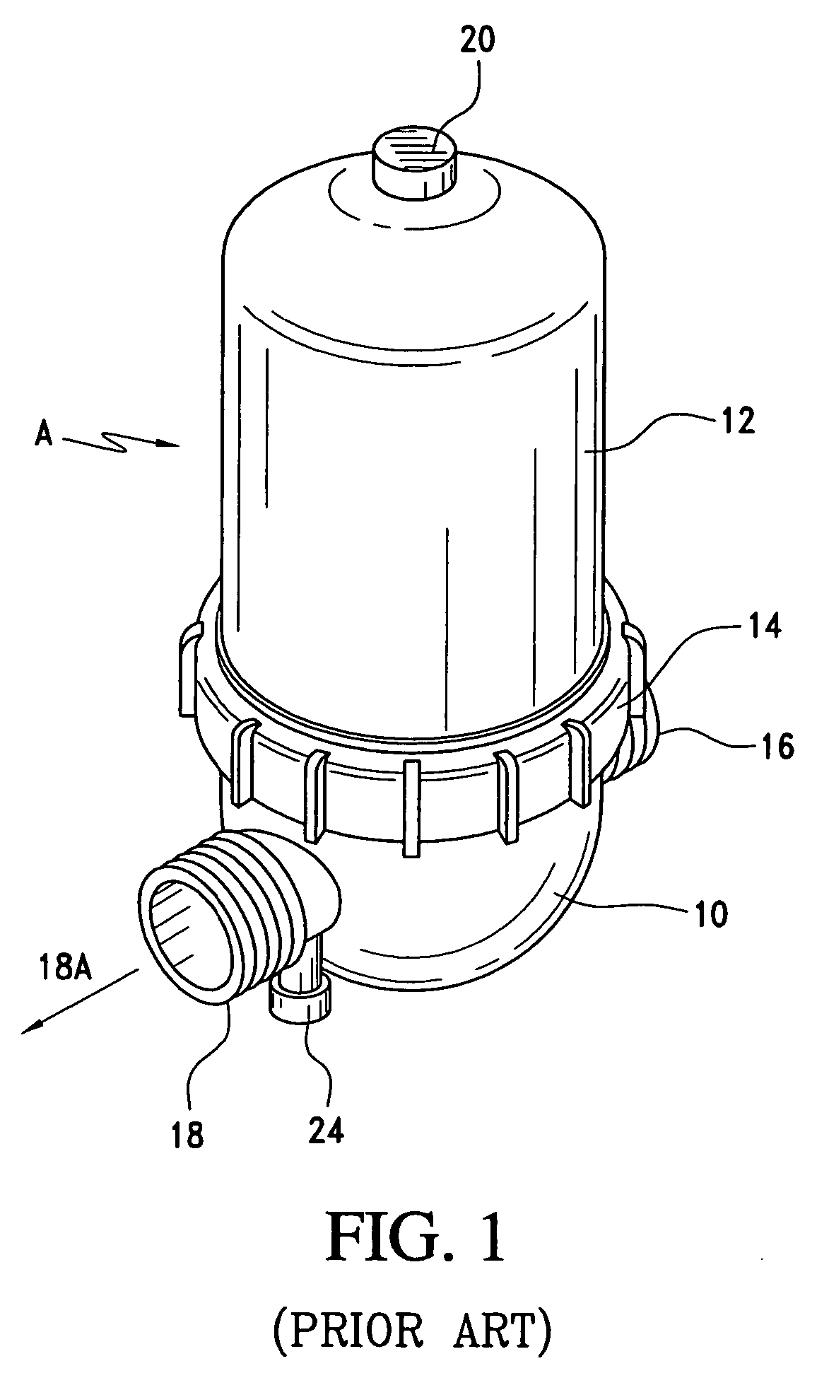
Prior Art Manual Filter:

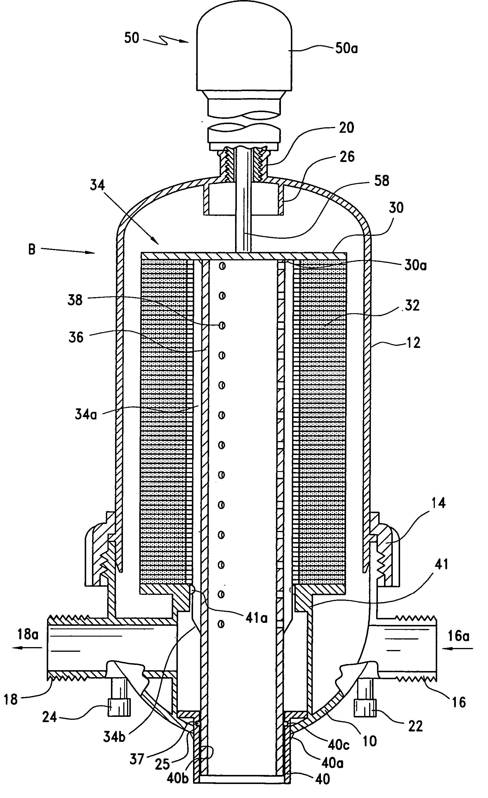
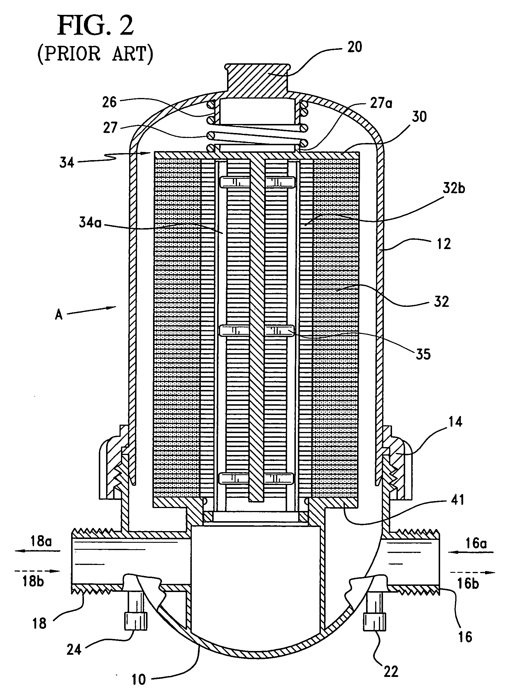
[0031]FIG. 1 shows the outside view of a conventional prior art manual ring disc filter assembly generally referred to by the letter A. FIG. 2 shows a sectional view of the manual ring disc filter assembly A of FIG. 1. The manual ring disc filter assembly has a body 10 that includes an inlet 16 and an outlet 18. The housing 12 is attached to the body 10 with a threaded securing ring 14. On the top of the cover 12 is a port 20 that is generally provided molded in, undrilled and untapped as shown in FIGS. 1 and 2. An inlet pressure measuring port 22 and an outlet pressure measuring port 24 are provided to allow pressure measurements to be taken to determine the pressure drop across the ring disc filters 32. The inlet pressure measuring port 22 and outlet pressure measuring port 24 may secondarily be used to drain fluid from the inlet 16 and outlet 18, respectively. A stack of ring discs 32 are located on the spine 34 and positioned on t...


PUM

PropertyMeasurementUnit
angleaaaaaaaaaa
angleaaaaaaaaaa
angles of inclinationaaaaaaaaaa

Abstract

A self-cleaning filter system is disclosed that includes an inlet fitting that is adapted to be inserted into an existing filter body. A spray tube having a plurality of outlets that slideably engages the inlet fitting, is positioned in the ring discs of the existing filter and a compression member proximate to one end of the ring discs applies a compressive force to the ring discs. When fluid enters the spray tube from the inlet fitting compression on the ring discs is reduced to allow the ring discs to separate while fluid pressure is simultaneously imposed on the ring discs through a plurality of outlets to clean the filter component. The parts included with the system may be used to convert a manual filter into a self-cleaning filter system.

Description

BACKGROUND 37 C.F.R. § 1.77(b)(5) [0001] The present invention relates to filters and more particularly to a self-cleaning filter systems. The self-cleaning filter system cleans ring disc media effectively without the need to open and clean the filter manually. [0002] Ring disc filter elements were originally developed to filter hydraulic fluid for military aircraft and have gradually found widespread use in agricultural irrigation and in industrial applications. Ring discs are highly efficient in their ability to filter particulates from fluids. The ring discs are diagonally grooved on both sides to a specific micron size. A series of the ring discs are then stacked and compressed on a spine. When stacked, the grooves on top of each disc runs opposite from the grooves below it, creating a filtration system having a series of grooves and traps for solids. [0003] Agricultural irrigation systems that use ring disc filters are typically large scale and require high flow, high volume fi...

Claims


Application Information

Patent Timeline
Patent Type & Authority Applications(United States)
IPC IPC(8): B01D29/46B01D35/22
CPCB01D29/46B01D29/66
Inventor PROCHASKA, JAMES F.PROCHASKA, JUSTIN J.
Owner JNM TECH
Why Eureka
Try Eureka