Plasma reactor overhead source power electrode with low arcing tendency, cylindrical gas outlets and shaped surface

a technology of power electrode and overhead source, which is applied in the direction of arc welding apparatus, single unit paving, diaphragm, etc., can solve the problems of plasma process, further damage to the electrode, and arcing of the electrode surface,

Inactive Publication Date: 2005-08-18
APPLIED MATERIALS INC
View PDF7 Cites 107 Cited by
  • Summary
  • Abstract
  • Description
  • Claims
  • Application Information

AI Technical Summary

Benefits of technology

[0006] An overhead gas distribution electrode forming at least a portion of the ceiling of a plasma reactor has a bottom surface facing a processing zone of the reactor. The electrode includes a gas supply manifold for receiving process gas at a supply pressure at a top portion of the electrode and plural pressure-dropping cylindrical orifices extending axially relative to the electrode from the gas supply manifold at one end of each the orifice. ...

Problems solved by technology

The arcing can melt or sputter metal atoms from the electrode, creating contamination in the plasma and thereby causing the plasma process (e.g., a plasma-enhance reactive ion etch process carried out on a semiconductor workpiece) to fail.
Moreover, such arcing damages the electrode by widening different orifices, thereby distorting gas flow distribution at the electrode surface.
Finally, if the electrode is metal and is covered with a semiconductor protective layer, such arcing further damages the electrode or generates contamination by attacking the bonding adhesive placed between the semiconductive protective layer and the metallic electrode.
A very narrow gas outlet orifice diameter was employed in order to prevent migration of plasma into the gas outlet orifices, but this actually worsened the arcing problem.
Moreover, such narrow orifices were difficult to clean, so that residue from the plasma (e.g., polym...

Method used


Image

  • Plasma reactor overhead source power electrode with low arcing tendency, cylindrical gas outlets and shaped surface
  • Plasma reactor overhead source power electrode with low arcing tendency, cylindrical gas outlets and shaped surface
  • Plasma reactor overhead source power electrode with low arcing tendency, cylindrical gas outlets and shaped surface

Examples


Embodiment Construction

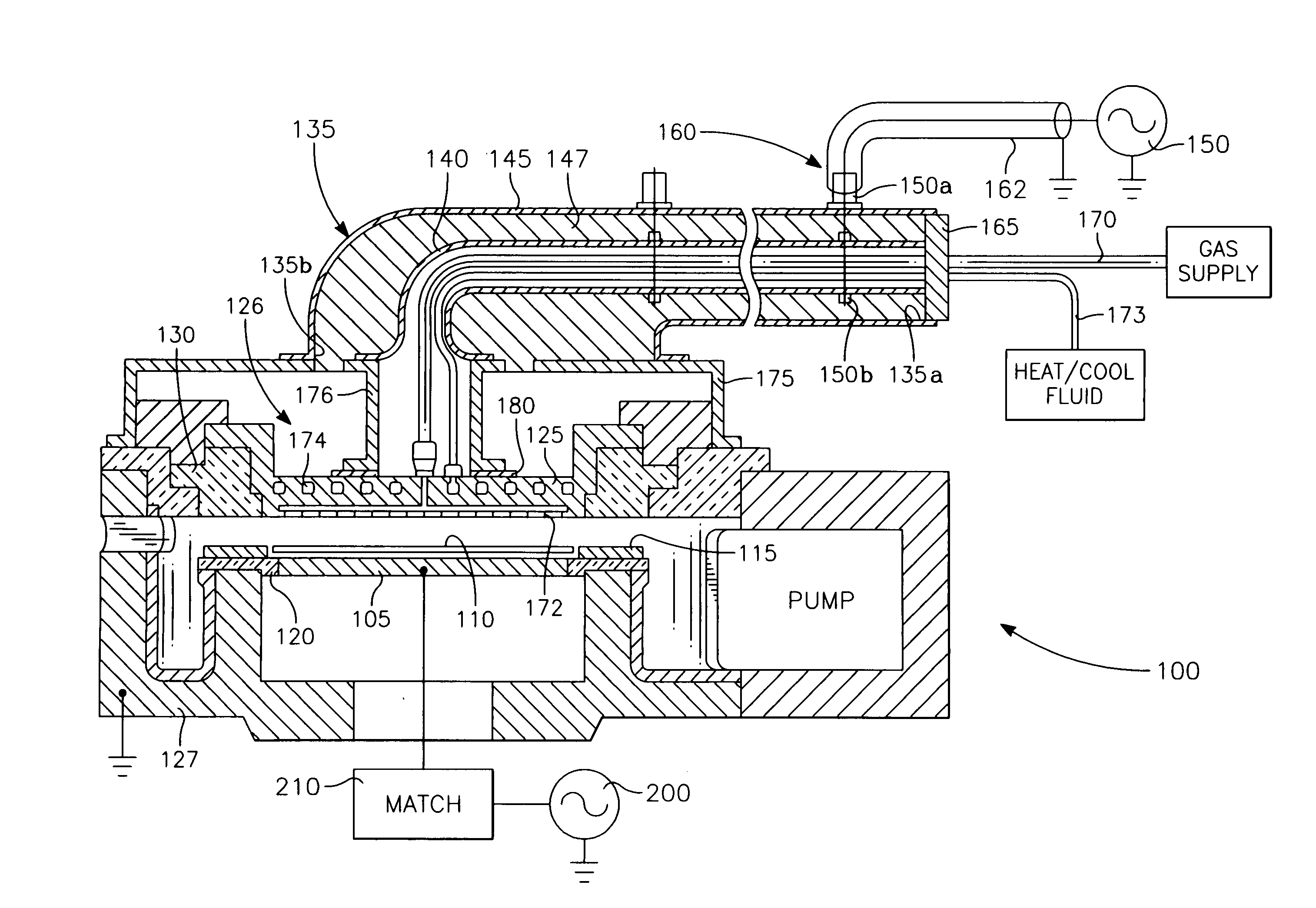
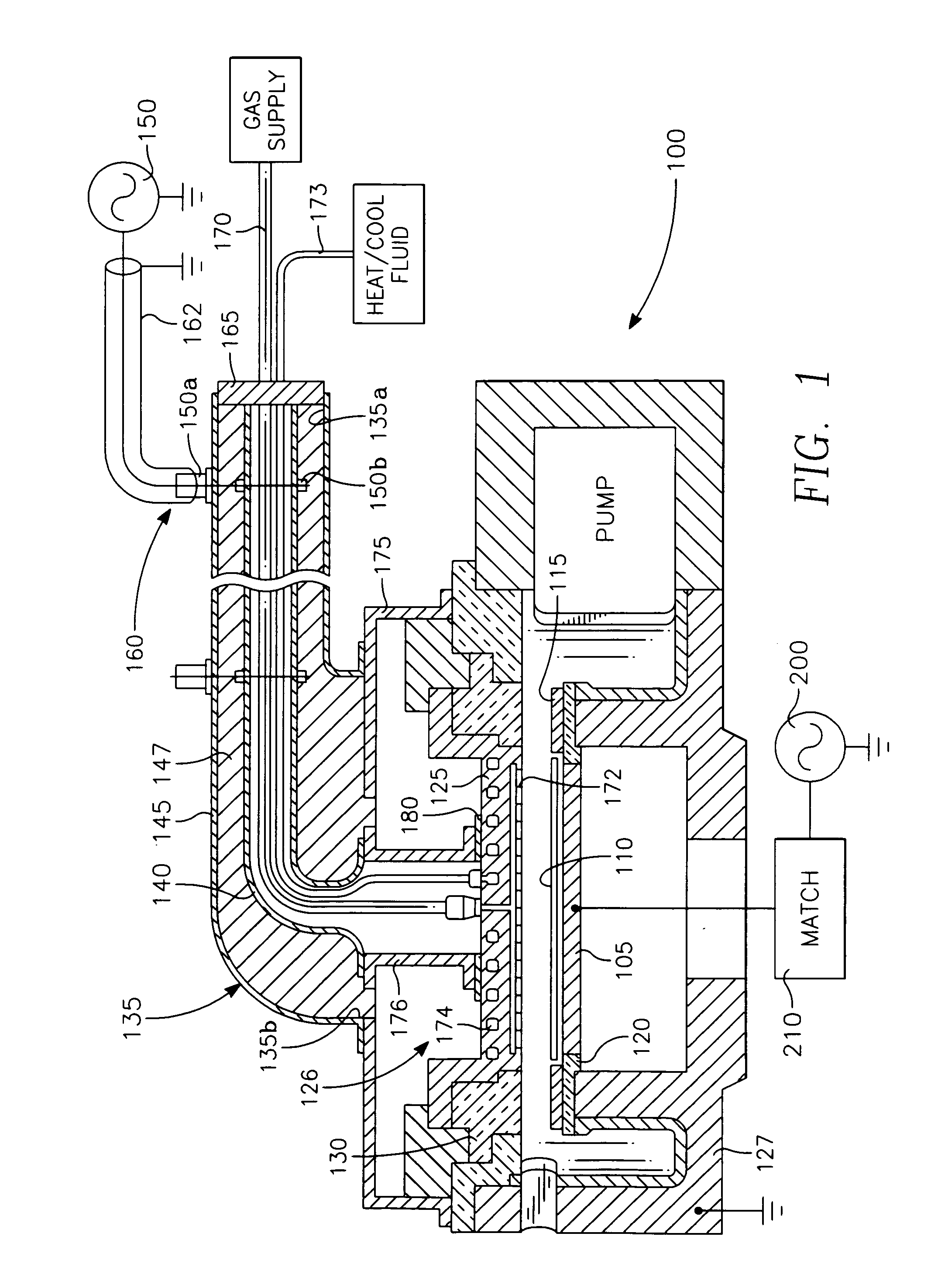
[0047] Referring to FIG. 1, a plasma reactor includes a reactor chamber 100 with a wafer support 105 at the bottom of the chamber supporting a semiconductor wafer 110. A semiconductor ring 115 surrounds the wafer 110. The semiconductor ring 115 is supported on the grounded chamber body 127 by a dielectric (quartz) ring 120. In one embodiment, this is of a thickness of 10 mm and dielectric constant of 4. The chamber 100 is bounded at the top by a disc shaped overhead aluminum electrode supported at a predetermined gap length above the wafer 110 on grounded chamber body 127 by a dielectric (quartz) seal. The overhead electrode 125 also may be a metal (e.g., aluminum) which may be covered with a semi-metal material (e.g., Si or SiC) on its interior surface, or it may be itself a semi-metal material. An RF generator 150 applies RF power to the electrode 125. RF power from the generator 150 is coupled through a coaxial cable 162 matched to the generator 150 and into a coaxial stub 135 co...


PUM

PropertyMeasurementUnit
Fractionaaaaaaaaaa
Fractionaaaaaaaaaa
Fractionaaaaaaaaaa

Abstract

An overhead gas distribution electrode forming at least a portion of the ceiling of a plasma reactor has a bottom surface facing a processing zone of the reactor. The electrode includes a gas supply manifold for receiving process gas at a supply pressure at a top portion of the electrode and plural pressure-dropping cylindrical orifices extending axially relative to the electrode from the gas supply manifold at one end of each the orifice. A radial gas distribution manifold within the electrode extends radially across the electrode. Plural axially extending high conductance gas flow passages couple the opposite ends of respective ones of the plural pressure-dropping orifices to the radial gas distribution manifold. Plural high conductance cylindrical gas outlet holes are formed in the plasma-facing bottom surface of the electrode and extend axially to the radial gas distribution manifold.

Description

CROSS-REFERENCE TO RELATED APPLICATIONS [0001] This application is a continuation-in-part of U.S. patent application Ser. No. 10 / 754,280, filed Jan. 8, 2004 entitled PLASMA REACTOR WITH OVERHEAD RF SOURCE POWER ELECTRODE WITH LOW LOSS, LOW ARCING TENDENCY AND LOW CONTAMINATION by Daniel J. Hoffman et al., which is a continuation-in-part of U.S. patent application Ser. No. 10 / 028,922, filed Dec. 19, 2001 entitled PLASMA REACTOR WITH OVERHEAD RF ELECTRODE TUNED TO THE PLASMA by Daniel Hoffman et al., which is a continuation-in-part of U.S. patent application Ser. No. 09 / 527,342, filed Mar. 17, 2000 entitled PLASMA REACTOR WITH OVERHEAD RF ELECTRODE TUNED TO THE PLASMA by Daniel Hoffman et al., now issued as U.S. Pat. No. 6,528,751, and all of which are assigned to the present assignee.BACKGROUND ART [0002] An overhead gas showerhead with many small gas inlet orifices can cause plasma arcing when used as an electrode to capacitively couple plasma source power. Plasma tends to enter int...

Claims


Application Information

Patent Timeline
IPC IPC(8): H01J37/32
CPCH01J37/32082H01J37/32091H01J37/3244H01J37/32183H01J37/32174E01C5/226E01C15/00
Inventor BUCHBERGER, DOUGLAS A. JR.HOFFMAN, DANIEL J.REGELMAN, OLGACARDUCCI, JAMESHORIOKA, KEIJIYANG, JANG GYOO
Owner APPLIED MATERIALS INC
Why Eureka
Try Eureka