Multipolarization radiating device with orthogonal feed via surface field line(S)

a multipolarization, surface field line technology, applied in the direction of resonant antennas, particular array feeding systems, antenna earthings, etc., can solve the problems of difficult to insert active equipment into the array mesh, adversely affect the resonant structure,

Inactive Publication Date: 2005-08-18
THALES SA
View PDF17 Cites 39 Cited by
  • Summary
  • Abstract
  • Description
  • Claims
  • Application Information

AI Technical Summary

Benefits of technology

[0017] In a first embodiment, the coupling means comprise a coplanar auxiliary feed line substantially perpendicular to the main feed line an

Problems solved by technology

This planar technology gives rise to a certain number of technical problems.
The feed circuit being placed on or under the radiating ground plane, the resonant structure may be adversely affected by unwanted radiation or stray coupling.
The feed circuit being placed parallel to the ground plane, it is difficult to insert active equipments into the mesh of the array, such as low noise-amplifiers (LNA) or high-power amplifiers (HPA) and/or phase-shifter cells, whose dimensions are typically around 0.6 λ. This problem is accentuated if the arra

Method used


Image

  • Multipolarization radiating device with orthogonal feed via surface field line(S)
  • Multipolarization radiating device with orthogonal feed via surface field line(S)
  • Multipolarization radiating device with orthogonal feed via surface field line(S)

Examples


first embodiment

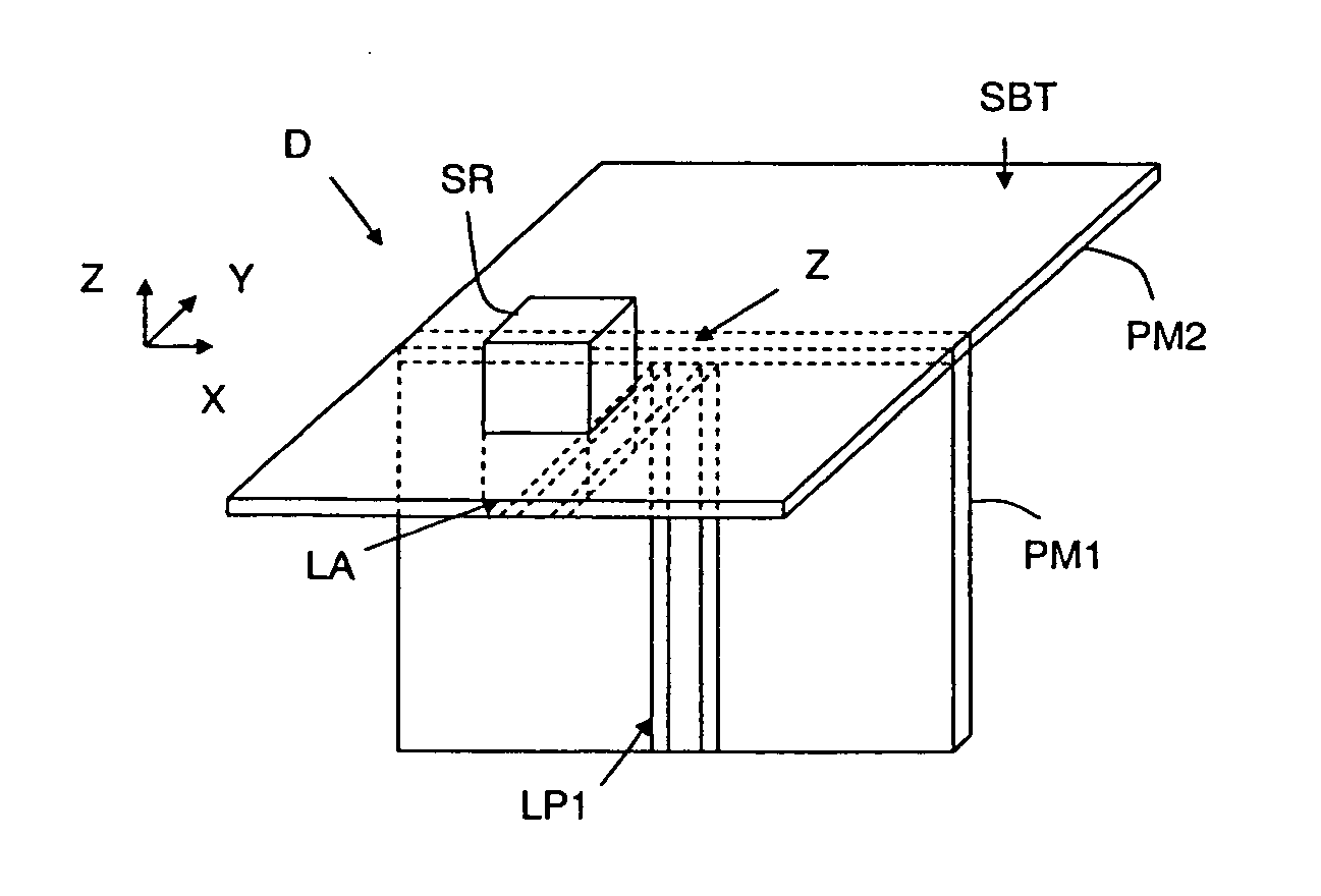
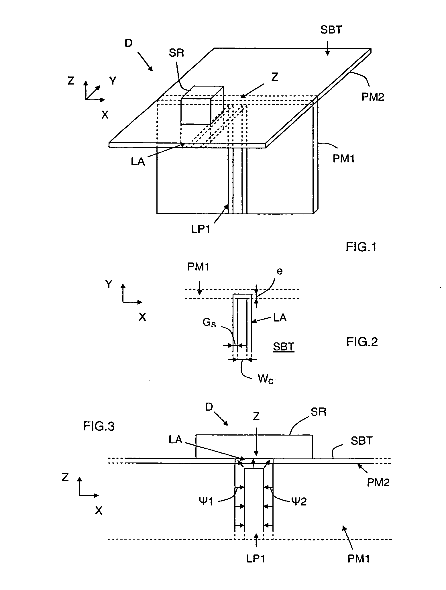
[0072] a radiating device D of the invention suitable for monopolarization is described first with reference to FIGS. 1 to 3.

[0073] A radiating device D of the invention comprises firstly a first ground plane PM1 disposed in an XZ plane and including one or more surface electric field main feed lines LP1 adapted to be connected to antenna equipments, for example an amplifier integrated circuit, such as an MMIC (where applicable including a low-noise amplifier (LNA) or a high-power amplifier (HPA)), or a phase-shifter cell. In this first embodiment, the surface electric field feed line LP1 is a coplanar line, but it could be a slotted (or microslotted) line, as explained hereinafter.

[0074] The device D also comprises a second ground plane PM2, disposed in a plane XY substantially perpendicular to the first ground plane PM1, preferably electrically connected to the latter at least near the main feed line LP1, and including electromagnetic coupling means fed orthogonally by a first en...

second embodiment

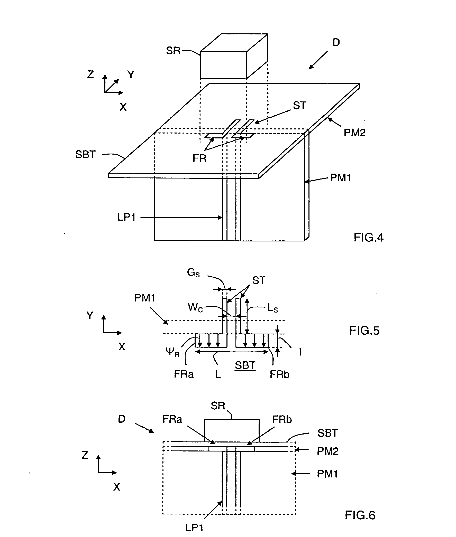
[0083] a radiating device D of the invention, also suitable for monopolarization, is described next with reference to FIGS. 4 to 9.

[0084] This second embodiment differs from the first in terms of the coupling means formed on the second ground plane PM2. In this embodiment, as in all the others to be described hereinafter, the coupling means are implemented in the form of a coupling slot that is preferably at the center of the resonant structure SR to obtain maximum coupling and minimize higher modes in said radiating structure SR and consequently crossed polarization radiation. For reasons of compactness, it is possible to fold the coupling slot or to give it special shapes, for example a “T-bar” shape.

[0085] To be more precise, in this embodiment, as shown in FIGS. 4 to 6, the coupling slot FR is of generally rectangular shape but is interrupted in its central portion by a portion of the second ground plane. In other words, the coupling slot FR has two portions FRa and FRb.

[0086]...

fourth embodiment

[0095] a radiating device D of the invention, also suitable for monopolarization, is described next with reference to FIG. 11.

[0096] In this fourth embodiment, the first ground plane PM1 still comprises a coplanar main feed line LP1. However, here, firstly, the coupling slot FR′ has a rectangular general shape defined by a longitudinal Y direction (longer side) and a transverse X direction (shorter side), and, secondly, the upper end (ES) of the main feed line LP1 is bent at substantially 90° to place it under the coupling slot FR′ parallel to the transverse X direction.


PUM


Abstract

A radiating device for an antenna comprises a first ground plane comprising a surface electric field main feed line, a second ground plane substantially perpendicular to the first ground plane and comprising electromagnetic coupling means fed orthogonally by a first end of the main feed line, and a resonant structure adapted to radiate energy in the event of excitation by electromagnetic coupling at the first end of the main feed line via the coupling means.

Description

CROSS-REFERENCE TO RELATED APPLICATIONS [0001] This application is based on French Patent Application No. 04 50 284 filed 17 Feb. 2004, the disclosure of which is hereby incorporated by reference thereto in its entirety, and the priority of which is hereby claimed under 35 U.S.C. §119. BACKGROUND OF THE INVENTION [0002] 1. Field of the Invention [0003] The invention relates to the field of transmit and / or receive antennas, and more particularly to the radiating devices (or elements) of such antennas. [0004] 2. Description of the Prior Art [0005] In the present context the term “radiating device” means a combination comprising at least a main feed line, a radiating ground plane and a resonant structure for radiating energy at a selected wavelength λ when it is excited by the main feed line, where applicable via coupling means forming part of the radiating ground plane. [0006] The term “antenna” means not only conventional antennas such as focal array antennas, for example FAFR or pas...

Claims


Application Information

Patent Timeline
IPC IPC(8): H01Q9/04H01Q21/00
CPCH01Q21/0006H01Q9/0457H01Q9/0485
Inventor LEGAY, HERVELATHIERE, GUILLAUMEGILLARD, RAPHAEL
Owner THALES SA
Why Eureka
Try Eureka