Light emitting device and method of driving the same
a technology of light emitting devices and driving transistors, applied in static indicating devices, solid-state devices, instruments, etc., can solve problems such as weakening the resistance of driving transistors to fluctuation in characteristic characteristics
- Summary
- Abstract
- Description
- Claims
- Application Information
AI Technical Summary
Benefits of technology
Problems solved by technology
Method used
Image
Examples
embodiment 1
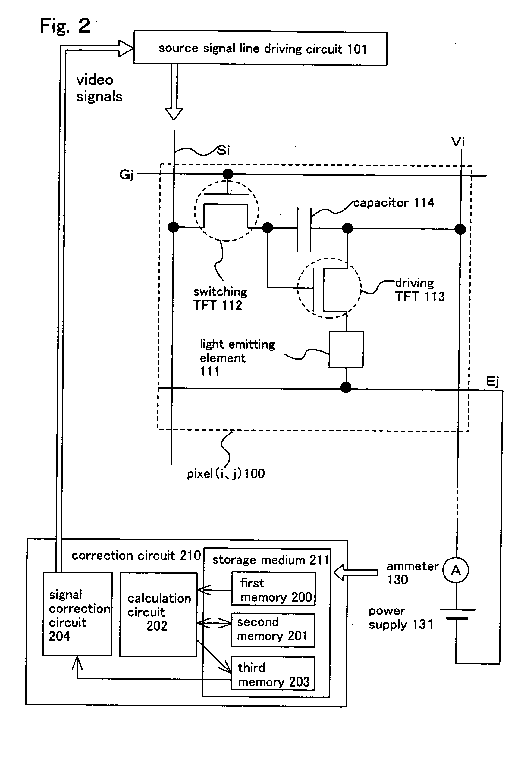
[0135] The present invention is also applicable to a light emitting device with a pixel having a structure different from the one in FIG. 2. This embodiment describes an example thereof with reference to FIG. 6 and FIGS. 18B and 18C.
[0136] A pixel (i, j) shown in FIG. 6 has a light emitting element 311, a switching transistor 312, a driving transistor 313, an erasing transistor 315, and a capacitor storage 314. The pixel (i, j) is placed in a region surrounded by a source signal line (Si), a power supply line (Vi), a gate signal line (Gj), and an erasing gate signal line (Rj).
[0137] A gate electrode of the switching transistor 312 is connected to a gate signal line (Gj). The switching transistor 312 has a source region and a drain region one of which is connected to a source signal line (Si) and the other of which is connected to a gate electrode of the driving transistor 313. The switching transistor 312 is a transistor functioning as a switching element when a signal is inputted...
embodiment 2
[0153] This embodiment describes an example of sectional structure of a pixel with reference to FIG. 7.
[0154] In FIG. 7, a switching transistor 4502, which is an n-channel transistor formed by a known method, is provided on a substrate 4501. The transistor in this embodiment has a double gate structure. However, a single gate structure, a triple gate structure, or a multi-gate structure having more than three gates may be employed instead. The switching transistor 4502 may be a p-channel transistor formed by a known method.
[0155] A driving transistor 4503 is an n-channel transistor formed by a known method. A drain wire 4504 of the switching transistor 4502 is electrically connected to a gate electrode 4506 of the driving transistor 4503 through a wire (not shown in the drawing).
[0156] The driving transistor 4503 is an element for controlling the amount of current flowing in a light emitting element 4510, and a large amount of current flows through the driving transistor to raise...
embodiment 3
[0180] In this embodiment, an appearance view of the light emitting device is described with reference to FIGS. 8A to 8B.
[0181]FIG. 8A is a top view of the light emitting device, FIG. 8B is a cross sectional view taken along with a line A-A′ of FIG. 8A, and FIG. 8C is a cross sectional view taken along with a line B-B′ of FIG. 8A.
[0182] A seal member 4009 is provided so as to surround a pixel portion 4002, a source signal line driving circuit 4003, and the first and the second gate signal line driving circuits 4004a, 4004b, which are provided on a substrate 4001. Further, a sealing material 4008 is provided on the pixel section 4002, the source signal line driving circuit 4003, and the first and the second gate signal line driving circuits 4004a, 4004b. The pixel section 4002, the source signal line driving circuit 4003, and the first and the second gate signal line driving circuits 4004a, 4004b are sealed by the substrate 4001, the seal member 4009 and the sealing material 4008 t...
PUM
 Abstract
Description
Claims
Application Information
 - R&D
- Intellectual Property
- Life Sciences
- Materials
- Tech Scout
- Unparalleled Data Quality
- Higher Quality Content
- 60% Fewer Hallucinations
Browse by: Latest US Patents, China's latest patents, Technical Efficacy Thesaurus, Application Domain, Technology Topic, Popular Technical Reports.
© 2025 PatSnap. All rights reserved.Legal|Privacy policy|Modern Slavery Act Transparency Statement|Sitemap|About US| Contact US: help@patsnap.com


