Method and apparatus for image registration improvements in a printer having plural printing stations

a technology of printers and printers, applied in the field of apparatus and methods for controlling the temperature of print heads in the printer apparatus, can solve the problems of poor registration, deterioration of print quality, and difficulty in properly aligning the color separations on the receiver to give crisp, high-quality images, so as to achieve the effect of maximizing the accuracy of temperature measuremen

Active Publication Date: 2005-08-18
KODAK ALARIS INC
View PDF5 Cites 15 Cited by
  • Summary
  • Abstract
  • Description
  • Claims
  • Application Information

AI Technical Summary

Benefits of technology

[0011] We have shown experimentally that other sensors in the receiver conveyance path can be used in the same manor as the sensor to measure the receiver temperature. One specific location for an additional sensor would be located in contact with the mechanism capstan drive roller, which transports the receiver during printing. The capstan drive roller is located beyond all of the print stations and accumulates thermal energy as the receiver is transported by the capstan drive roller during printing. Sensing this temperature can be utilized to approximate the paper temperature. The advantage of multiple sensors is to maximize the accuracy of the temperature measurement.

Problems solved by technology

A problem with printer apparatus of the type described above is the difficulty of properly aligning the color separations on the receiver to give crisp, high quality images.
Even when the print heads are accurately positioned and relative to the print drum or to the receiver pathway, there still exists the possibility for poor registration which deteriorates print quality.
There is a possibility for misregistration in the direction of travel of the receiver because the receiver may stretch or become misaligned on the drum.
Even when these causes of poor registration are negated, there exists a risk of improper color separation alignment due to changes in the velocity of the image receiver as a function of changes in the temperature of the receiver.
It has been determined that the penetration depth of the drive features of a capstan roller of the receiver conveyance system is one cause of this change in receiver velocity.
This change results in reducing the transport velocity of the receiver.

Method used


Image

  • Method and apparatus for image registration improvements in a printer having plural printing stations
  • Method and apparatus for image registration improvements in a printer having plural printing stations
  • Method and apparatus for image registration improvements in a printer having plural printing stations

Examples


Embodiment Construction

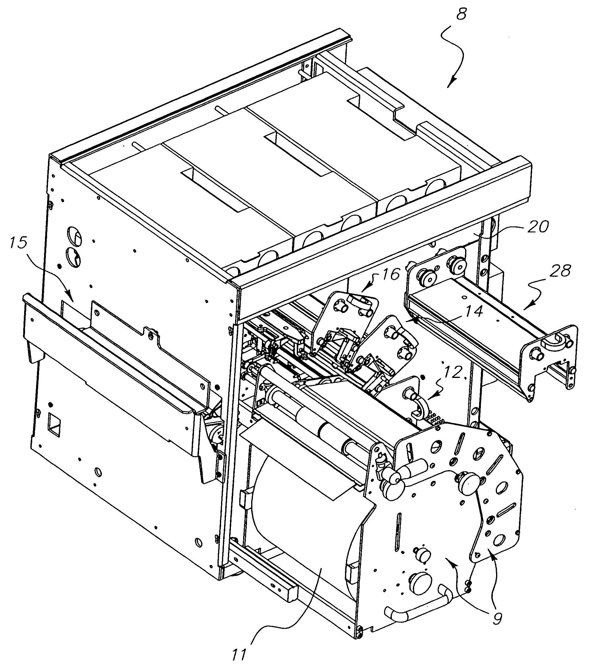
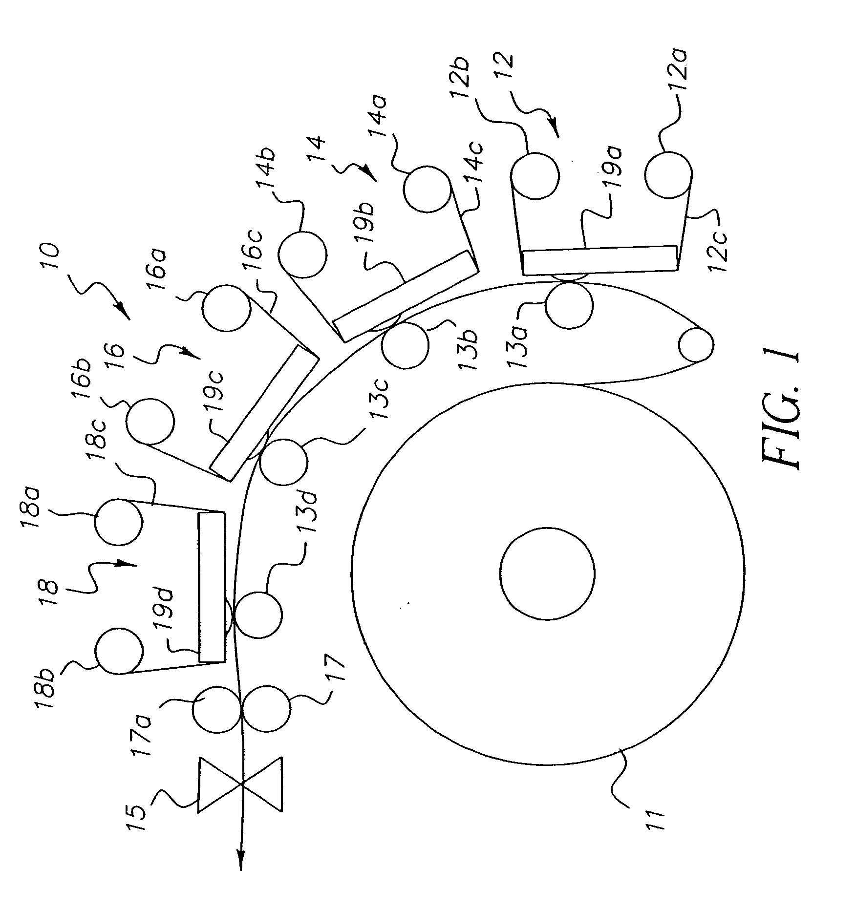
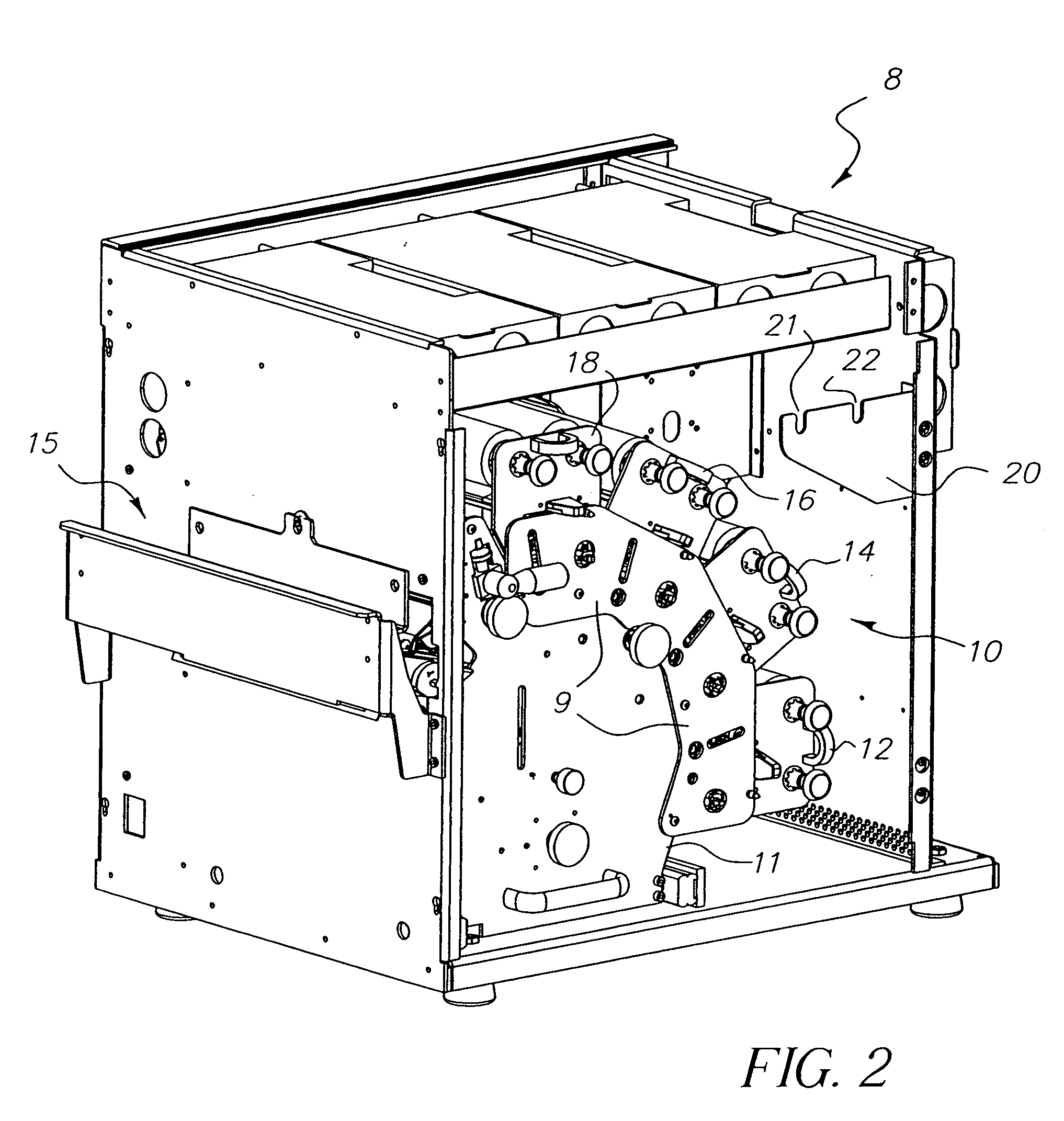
[0023] Referring to FIG. 1, the invention will be described with reference to a single pass, multi-color thermal printer of the type described in U.S. Pat. No. 5,440,328. In such a printer, a print engine 10 is provided that comprises a receiver transport system and three or more thermal print head assemblies 12, 14 and 16. Each of the print head assemblies includes a respective re-loadable thermal ribbon cassette assembly which is loaded with a color transfer ribbon 12c, 14c and 16c. Each of the thermal print head assemblies comprises a thermal print head 19a-d having a thermal print line. Each of the print head assemblies further has a counterpart platen roller 13a-c with which a respective print head forms a respective nip and through which a receiver 11 passes in combination with the respective color ribbon of dye. The mounting assemblies allow the print heads' positions to be adjusted so that the mounting assemblies can be pivoted towards and away from the respective platen rol...


PUM


Abstract

A thermal printer apparatus has a plurality of print stations for recording image information onto a receiver moving past the print stations. An adjustable-speed receiver drive mechanism is adapted to advance the receiver along the path. A plurality of sensors adapted to detect the temperature of the receiver and other surfaces along the path. A controller adjusts the speed of the drive mechanism as a function of the detected temperatures so as to effect a shim of the average raster line pitch of the printer to compensate for changes in the temperature of the receiver. An empirical model of receiver speed as a function of measured receiver temperature is used in software to predict receiver speed during printing.

Description

BACKGROUND OF THE INVENTION [0001] 1. Field of the Invention [0002] The present invention relates to apparatus and methods for controlling temperature of print heads in a printer apparatus. More particularly, the present invention is directed to a print engine that comprises plural printing stations. [0003] 2. Description Relative to the Prior Art [0004] In the prior art as represented by U.S. Pat. No. 5,440,328, thermal printer apparatus are known that operate as a single pass, multi-color thermal printer. In such a printer a print engine is provided that comprises a receiver transport system and three or more thermal print head assemblies. Each of the print head assemblies includes a respective reloadable thermal ribbon cassette which is loaded with a respective color transfer ribbon. Each of the thermal print head assemblies comprises a cantilevered beam, a mounting assembly and a thermal print head having a thermal print line. Each of the print head assemblies has a counterpart ...

Claims


Application Information

Patent Timeline
Patent Type & Authority Applications(United States)
IPC IPC(8): B41J2/32B41J2/325B41J11/42
CPCB41J2/325
Inventor GOFF, COBB S.ELLY, JAMES E.GUGINO, RICHARD L.BERRY, JEFFREY R.
Owner KODAK ALARIS INC
Why Eureka
Try Eureka