Vehicle lamp unit

a technology for lamps and lampshades, applied in fixed installations, lighting and heating apparatus, lighting support devices, etc., can solve the problem of large horizontal diffusion angle, horizontal elongation of light distribution patterns, and inability to form horizontal diffusion patterns, etc., to achieve the effect of increasing the utilization rate of light flux

Inactive Publication Date: 2005-08-18
KOITO MFG CO LTD
View PDF14 Cites 42 Cited by
  • Summary
  • Abstract
  • Description
  • Claims
  • Application Information

AI Technical Summary

Benefits of technology

[0023] As shown in the above configuration, the vehicle lamp unit according to the invention is configured such that the translucent member is disposed so as to cover the light-emitting element—which is disposed on the optical axis extending in the front-rear direction of the lamp unit so as to face forward—from the front side thereof. Accordingly, a utilization rate of the light flux in relation to light from the light-emitting element can be increased.
[0027] As described above, according to the present invention, the vehicle lamp unit—which employs a light-emitting element as a light source—can form a horizontally-elongated light distribution pattern whose horizontal diffusion angle is large, in addition to increasing a utilization rate of the light flux in relation to light from the light-emitting element.
[0029] In addition, in the above configuration, when at least one of the pair of exit surfaces is formed as a downward-deflection surface for causing light having been internally reflected by the reflection surface and reached the exit surface to exit in a downwardly deflected manner, the following working-effects can be obtained. That is, when only one of the exit surfaces is configured as a downward-deflection surface, two horizontally-elongated light distribution patterns can be formed at positions which are vertically displaced. Furthermore, when both of the exit surfaces are configured as downward-deflection surfaces, the position of the horizontally-elongated light distribution pattern can be displaced downward with the lamp unit being maintained such that the optical axis thereof extends horizontally.
[0031] In the above configuration, when the following configuration is employed, even in a case where the front-rear lengths of the pair of exit surfaces are set short, a utilization rate of the light flux in relation to light from the light-emitting element can be increased. That is, the pair of incidence surfaces are formed at positions which are vertically separated from each other; a portion which is on the rear face of the translucent member and which is between the two incidence surfaces is formed as a second incidence surface for allowing light emitted by the light-emitting element to enter while being deflected close to the optical axis in the vertical direction; a portion which is on the front face of the translucent member and which is between the two exit surfaces is formed as a second exit surface for causing light emitted by the light-emitting element and having entered the translucent member through the second incidence surface to exit forward from the translucent member in such a manner as to diffuse light in the horizontal direction and not to diffuse in the vertical direction. By virtue of the above configuration, the translucent member can be reduced in front-rear length, thereby enabling compact configuration of the lamp unit.

Problems solved by technology

However, there remains a related art problem, in that a horizontally-elongated light distribution pattern whose horizontal diffusion angle is large cannot be formed by light radiation from the lamp unit.

Method used


Image

  • Vehicle lamp unit
  • Vehicle lamp unit
  • Vehicle lamp unit

Examples


Embodiment Construction

[0046] Embodiments of the invention will be described hereinbelow by reference to the drawings.

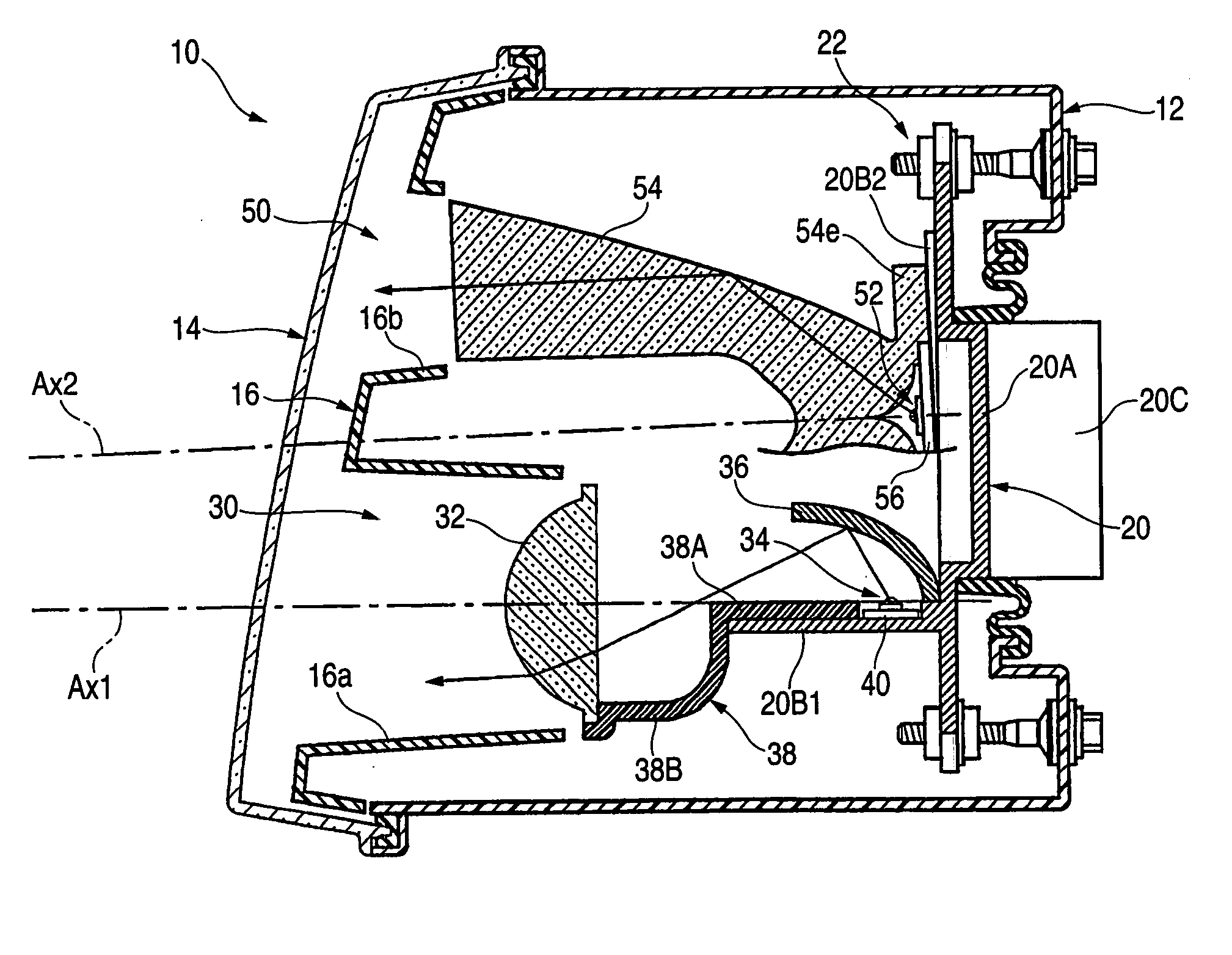
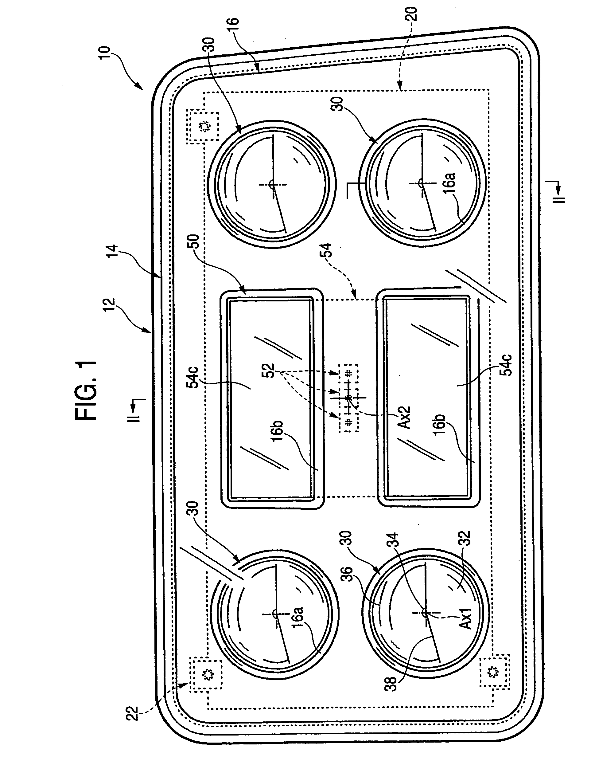
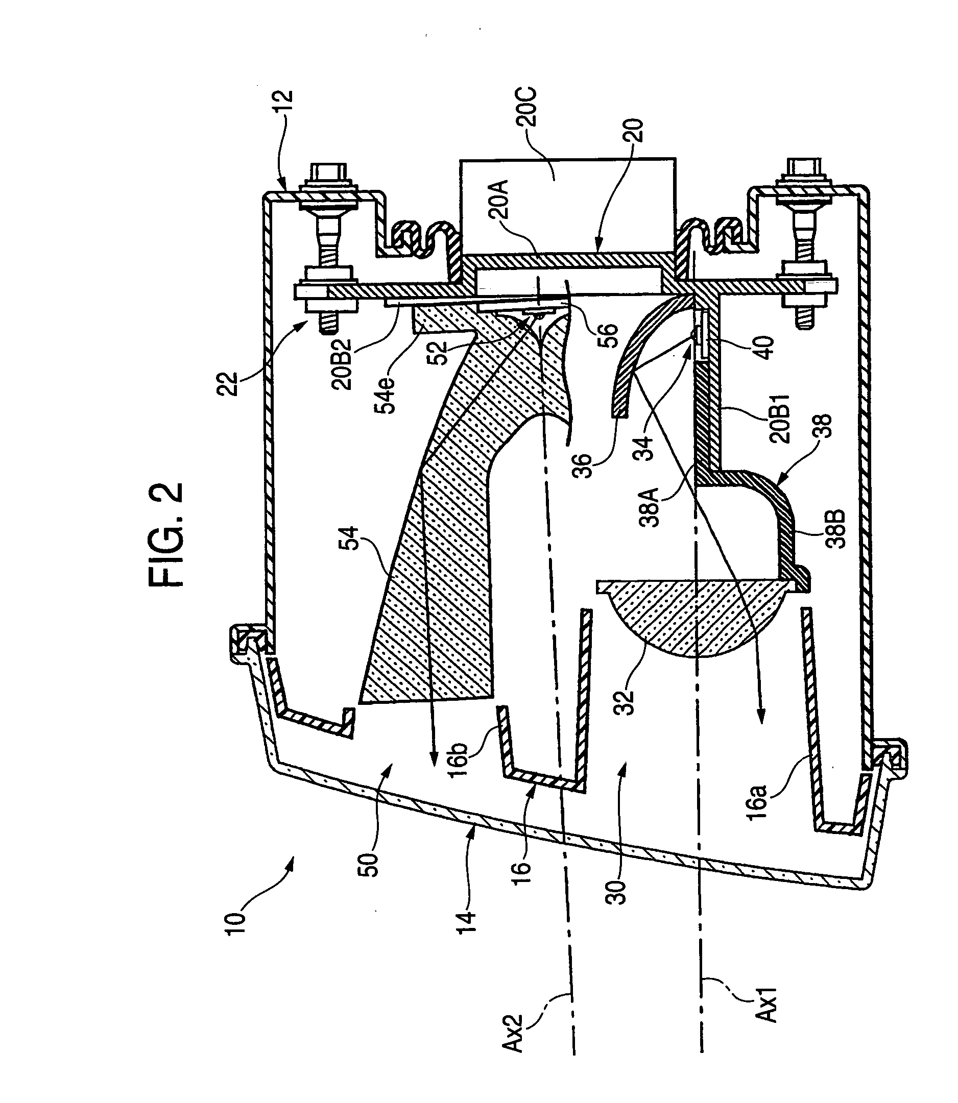
[0047]FIG. 1 is a front view showing a vehicle illumination lamp according to an exemplary, non-limiting embodiment of the present invention. FIG. 2 is across-sectional view taken along II-II of FIG. 1. A vehicle illumination lamp 10 is a headlamp disposed on the right side of the front end of a vehicle and configured such that five lamp units 30, 50 are housed within a lamp chamber. The lamp chamber is formed from a lamp body 12 and a clear translucent cover 14 which is attached to a front end opening of the lamp body 12.

[0048] Of the five lamp units 30, 50, the four lamp units 30 are set to have an external shape which is substantially circular when viewed from the front, and are disposed in two rows, upper and lower. The remaining, single lamp unit 50 is set to have an external shape which is substantially rectangular when viewed from the front, and is disposed at the center of the fo...


PUM


Abstract

A pair of upper and lower incidence surfaces are formed on a rear face of a translucent member disposed to cover three light-emitting elements. On upper and lower sides of the incidence surfaces are formed a pair of reflection surfaces for causing light emitted by the light-emitting elements and having entered the translucent member to internally reflect forward. Each of the incidence surfaces is formed from a cylindrical convex-curved surface extending horizontally. Each of the reflection surfaces is formed from a parabolic cylindrical curved surface whose focal line passes through a virtual image point of each of the light-emitting elements formed by the corresponding incidence surfaces. By the above configuration, light emitted by the light-emitting elements is caused to internally reflect in such a manner as to diffuse in the horizontal direction, and not to diffuse in the vertical direction, thereby exiting forward from a pair of exit surfaces.

Description

[0001] The present application claims foreign priority under 35 USC 119 based on Japanese Patent Application No. 2004-033397, filed on Feb. 10, 2004, the contents of which is incorporated herein by reference in its entirety, and concurrently with the filing of this U.S. patent application. BACKGROUND OF THE INVENTION [0002] 1. Technical Field [0003] The present invention relates to a vehicle lamp unit which employs a light-emitting element such as a light-emitting diode as its light source. [0004] 2. Background of the Related Art [0005] In recent years, a related art vehicle lamp unit which employs a light-emitting diode as a light source has been often adopted. [0006] In relation to the above, Japanese Patent Publication JP-A-2002-50214 discloses a vehicle lamp unit including a light-emitting diode disposed so as to face forward of the lamp unit, and a translucent member disposed so as to cover the light-emitting diode from the front side thereof. [0007] The vehicle lamp unit is co...

Claims


Application Information

Patent Timeline
Patent Type & Authority Applications(United States)
IPC IPC(8): F21S8/10F21V7/00F21S8/12F21V13/00F21Y101/02
CPCF21S48/1159F21S48/1163F21S48/1241F21S48/1329F21Y2101/02F21S48/25F21V5/04F21V7/0091F21S48/236F21Y2115/10F21S41/143F21S41/155F21S41/24F21S41/322F21S43/315F21S43/50F21S41/153F21S41/148
Inventor KOMATSU, MOTOHIRO
Owner KOITO MFG CO LTD
Why Eureka
Try Eureka