
Virtual network operator system, method and apparatus

a virtual network operator and network technology, applied in the field of virtual network operator system, method and apparatus, can solve the problems of difficult to increase or decrease the amount of bandwidth allocated to a particular network, considerable planning and expense, when adding a new network,

Active Publication Date: 2005-08-18
VT IDIRECT
View PDF3 Cites 30 Cited by
  • Summary
  • Abstract
  • Description
  • Claims
  • Application Information

AI Technical Summary

Benefits of technology

[0020] Accordingly, one object of the invention is to provide a novel scalable communication system, method, computer program product, and apparatuses. An embodiment of the communication system, method, computer program product, and apparatus includes common equipment shared between multiple independently administered networks. The common equipment is reconfigurable and expandable and provides changed communication capacity and functions when additional elements a

Problems solved by technology

Thus, considerable planning and expense are incurred when adding a new network.
As recognized by the present inventors, it is difficult to incrementally add capabilities for new users.
Also, it is difficult to increase or decrease the amount of bandwidth allocated to a particular network.
To increase the number of carriers allocated to a particular network (i.e., upstream) or adding a new network (i.e., modem group and associated equipment for a network) in the background art, it is necessary to add a teleport or add an additional hub modem chassis, thereby incurring significant capital expense.
However, in that alternative approach each network user does not have control over key network parameters like IP address assignment, QoS, number of upstreams, and frame lengths.
Further, this alternative background approach does not allow each user to customize the single network for their particular application (e.g., VoIP, web browsing, shared database, etc .
Thus, customers are not able to independently take advantage of all network features and are required to coordinate the control of those features with a third party network operator, thereby increasing expense and reducing customer flexibility and autonomy.
Alternatively, to get flexible control over these network parameters, each user of the background approach would disadvantageously need to spend additional money to set up independent networks dedicated to their application and tailored to their needs.
The present inventors recognized that a problem with this method of configuring a satellite communication network is that as configuration parameters are changed, those changes may cause undesirable temporary effects in the communication network.
Further, those effects may ripple through the communication network, causing problems that are more difficult to repair.
For example, when changing the IP address in the example shown above, after changing the IP address on the remote user software, a remote user loses the ability to communicate on the IP network, and may start a communication recovery action that may include sending messages to a domain name server for example, or may include other error recovery attempts that in turn may result in other errors that must be corrected.
Consequently, operation of such a communication system may be disadvantageously disrupted during a change of configuration.
Thus, users of the background satellite network system do not have a mechanism for independently defining IP addresses to allow independent assignment of IP addresses that may be the same, if multiple users each want some equipment to have the same IP address.
Moreover, this conventional system must coordinate with customer to make changes to remotes because the system does not provide a mechanism for network operators to easily make changes themselves without remote user involvement.
In addition, because configuration changes are made one remote at a time, configuration changes are time consuming and may disadvantageously take a long time to complete.

Method used


Image

  • Virtual network operator system, method and apparatus
  • Virtual network operator system, method and apparatus
  • Virtual network operator system, method and apparatus

Examples


Embodiment Construction

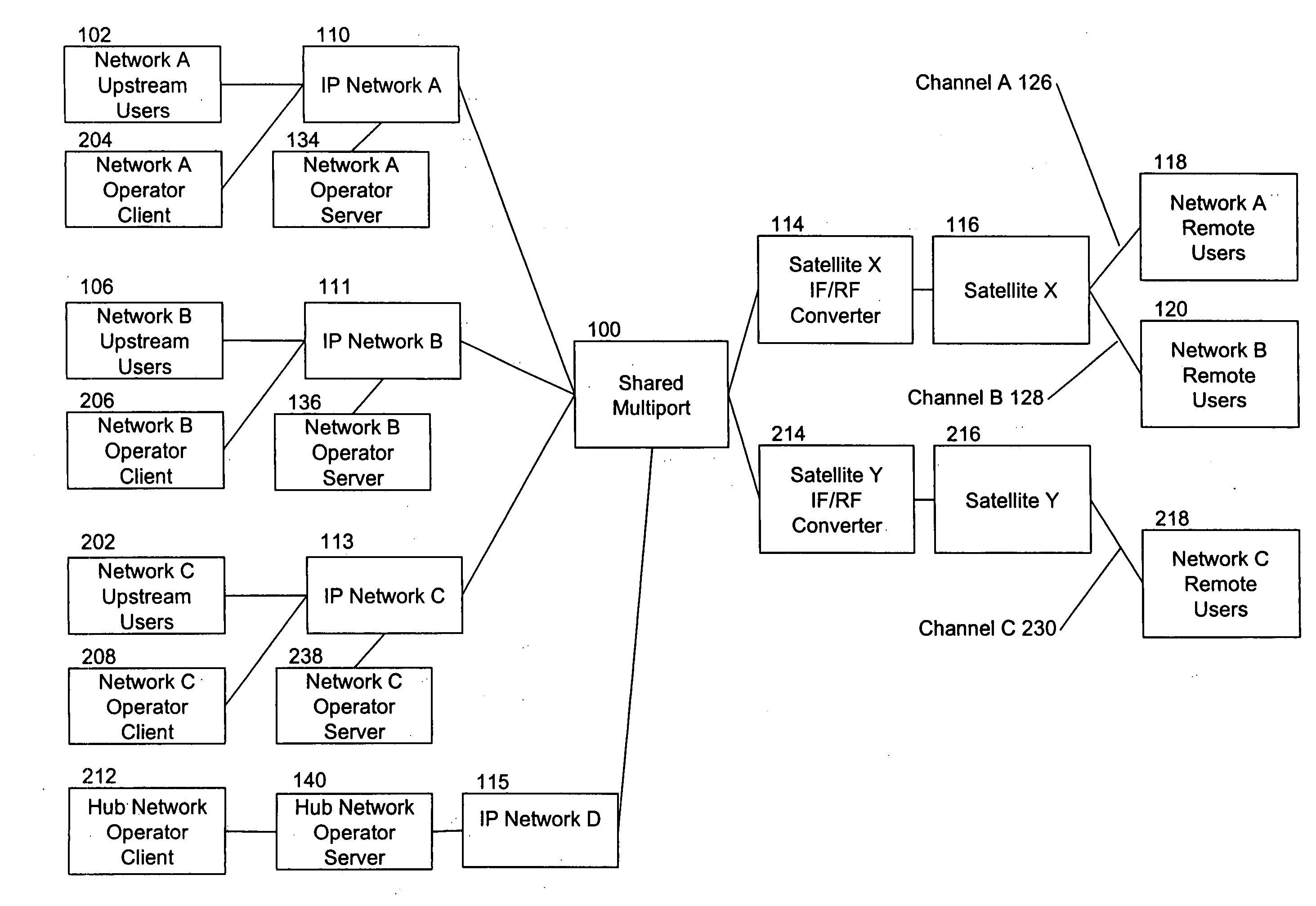
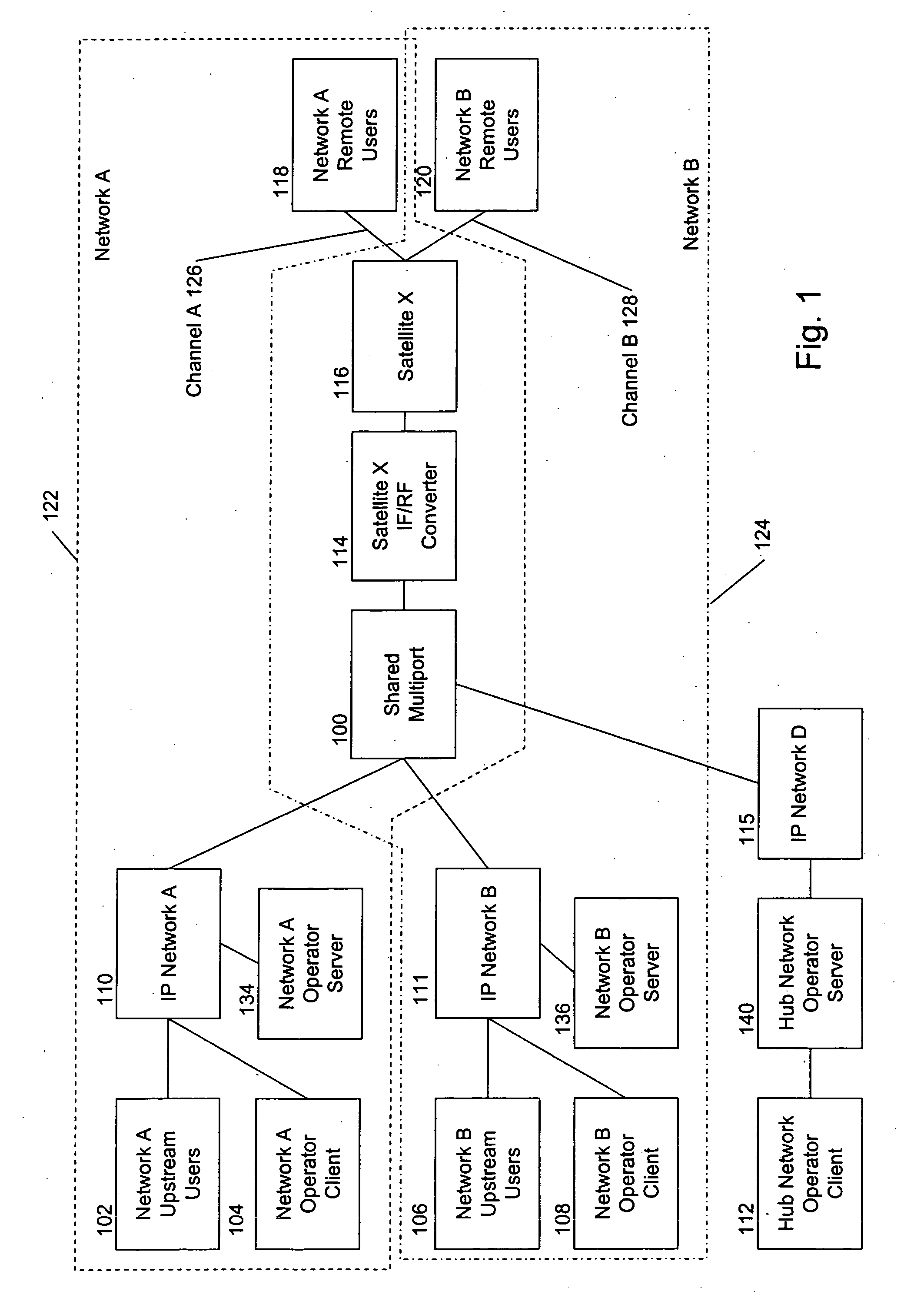
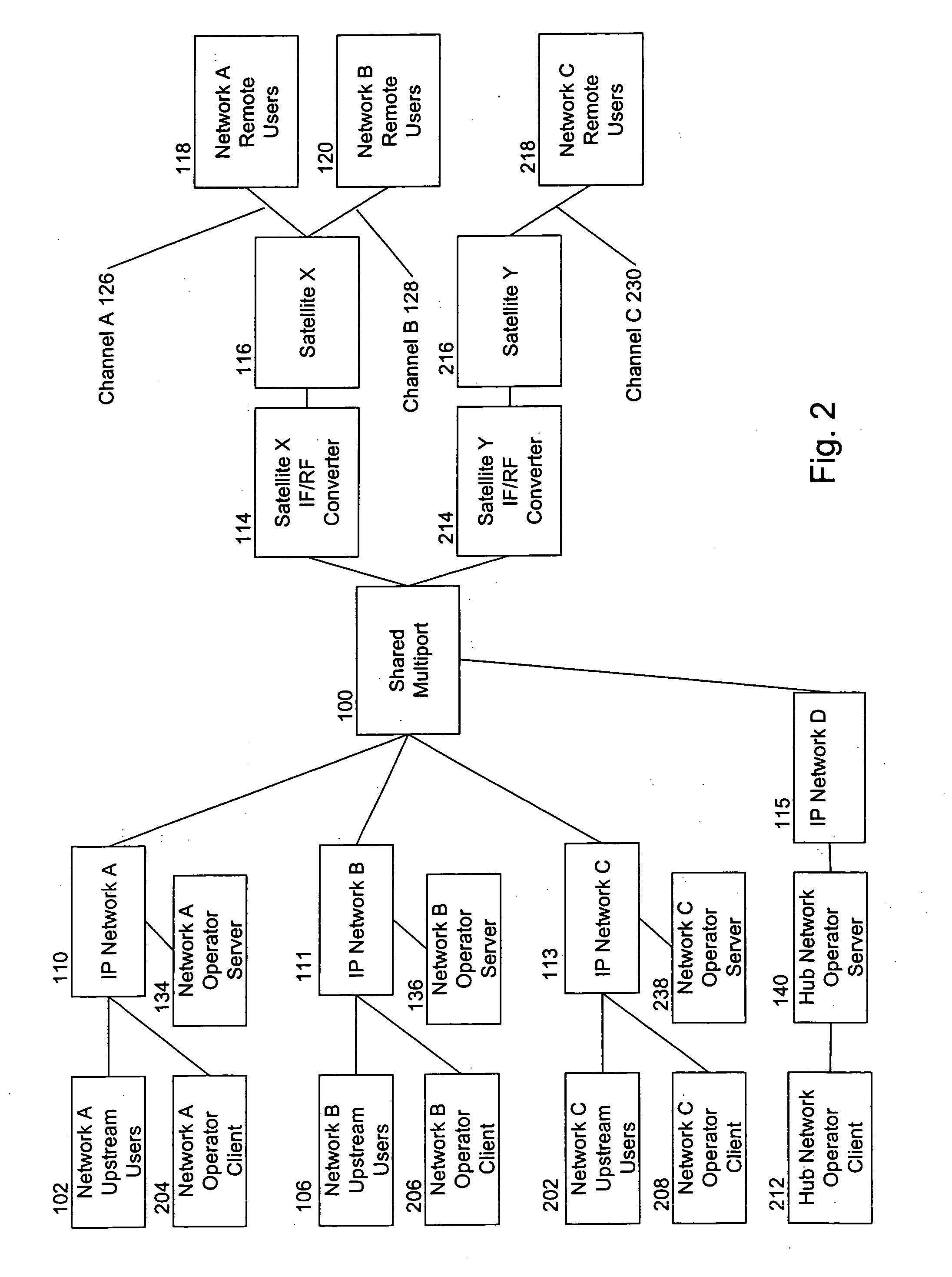
[0046] Referring now to the drawings, wherein like reference numerals designate identical or corresponding parts throughout the several views, FIG. 1 shows an example of a satellite communication system including shared independently administered satellite communication networks according to an embodiment of the present invention. In particular, FIG. 1 shows an example of two shared independently administered satellite communication networks, network A 122 and network B 124. Further, it should be noted that although the description herein includes examples of satellite communication networks, the inventions also pertains to and includes communication networks that do not include satellites.

[0047] Network A 122 includes network A upstream users 102 and network A operator 104 connected by IP network 110 to a shared multiport 100. Network A operator 104 provides management functions for network A, as discussed later in this specification. Further, network A 122 includes satellite X IF...


PUM


Abstract

A communication system, method, computer program product, and apparatus include common equipment shared between multiple independently administered networks. The common equipment is reconfigurable and expandable and provides changed communication capacity and functions when additional elements are added or reconfigured. Configurable features include, for example, communication bandwidth, Quality of Service, and a number of communication satellites included in the communication system. The common equipment includes expandable elements including, for example, a single hub modem chassis that can expand to communicate with more than one communication satellite and a protocol processor that can share a protocol processing task with another protocol processors.

Description

CROSS REFERENCE TO RELATED APPLICATIONS [0001] The present application contains subject matter related to that disclosed in commonly owned U.S. patent application Ser. No. [to be determined], attorney docket #252825US, entitled HUB MODEM SYSTEM, METHOD AND APPARATUS, filed Dec. 16, 2004; U.S. patent application Ser. No. [to be determined], attorney docket # 263379US, entitled CONFIGURATION STATE MANAGEMENT SYSTEM, METHOD AND APPARATUS, filed Dec. 16, 2004; U.S. patent application Ser. No. [to be determined], attorney docket # 263380US, entitled VIRTUAL ROUTER SYSTEM, METHOD AND APPARATUS, filed Dec. 16, 2004; and U.S. patent application Ser. No. [to be determined], attorney docket # 263384US, entitled SCALABLE COMMUNICATION SYSTEM, METHOD AND APPARATUS, and claims priority to copending U.S. provisional patent application Ser. No. 60 / 530,264, entitled NETWORK MANAGEMENT SYSTEM, filed Dec. 18, 2003, and copending U.S. provisional patent application Ser. No. 60 / 543,537, entitled METHOD...

Claims


Application Information

Patent Timeline
IPC IPC(8): H04B7/185
CPCH04B7/18597
Inventor BURDICK, CHRISTOPHER ROBERTRAY, DAVID EDWARDIONITA, NICOLETA
Owner VT IDIRECT
Learn More