Medium streaming distribution system

a distribution system and media technology, applied in television systems, two-way working systems, frequency-division multiplexes, etc., can solve the problems of increasing the packet loss resiliency of the encoding of the media, reducing the transmission rate of the media stream, and requiring a considerable amount of time to achieve the effect of improving communication quality

Active Publication Date: 2005-08-18
QUALCOMM INC
View PDF9 Cites 162 Cited by
  • Summary
  • Abstract
  • Description
  • Claims
  • Application Information

AI Technical Summary

Benefits of technology

[0018] Furthermore, according to an embodiment of the present invention, a transmission rate from the media delivery apparatus to the relay apparatus and a transmission rate from there lay apparatus to the terminal are obtained based on the feedback from both the media stream relay device and the terminal, and a surplus band is used for retransmission or forward error correction on the side of greater transmission rate, thereby improving communication quality.

Problems solved by technology

When a packet loss has occurred due to the congestion in a wired network, the media server reduces the media stream transmission rate, and when packet loss has occurred due to an error in the wireless link, it increases the packet loss resiliency of the encoding of the media.
In this type of conventional technique, once a packet loss occurs, considerable time is required before packet loss resiliency is increased.
In a case where packets containing an I-picture in a video stream is discarded due to flow control in response to congestion in the wired network and packets of multiple subsequent P-pictures are then transmitted via a wireless link, the client is unable to reconstruct these P-pictures since the I-picture needed for reference to reconstruct the P-pictures is not available.
Furthermore, even when a P-picture is discarded, no subsequent P-pictures dependent on that P-picture can be reconstructed until the next I-picture is received.
However, in streaming where the media is reconstructed and played back in real time, retransmission may be too late in such a case where the buffer size of the client is small.
When packets are discarded due to the congestion in a wired network, reconstruction errors occur not only for the discarded packet but also for the P-pictures contained in subsequent packets successfully received.

Method used


Image

  • Medium streaming distribution system
  • Medium streaming distribution system
  • Medium streaming distribution system

Examples


Embodiment Construction

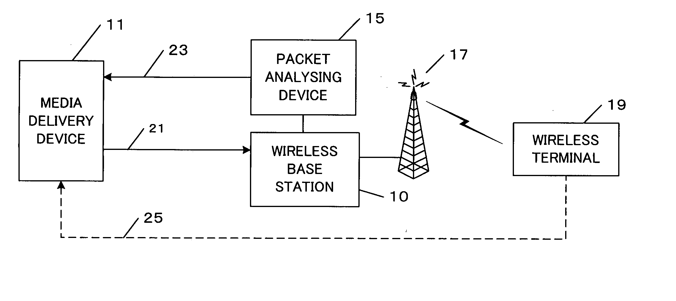
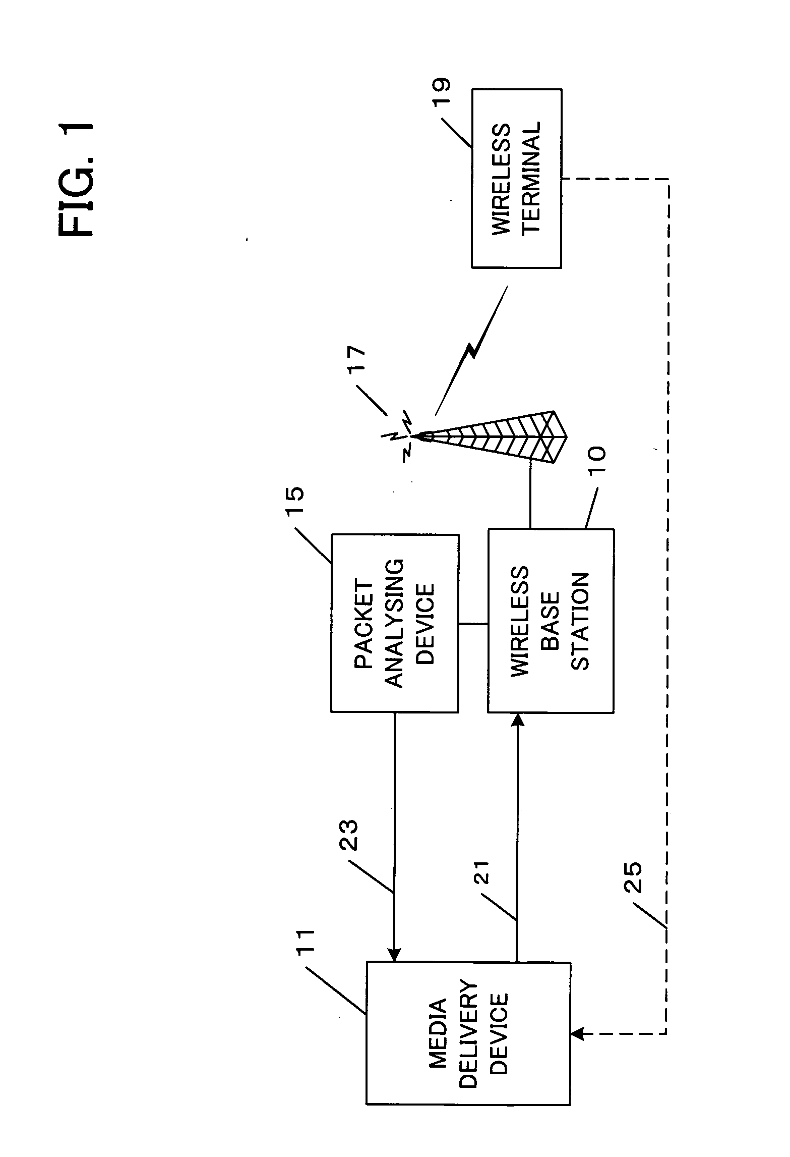
[0028] Hereinafter, an embodiment of the present invention will be explained with reference to the drawings. FIG. 1 is a diagram showing an overall construction of an embodiment of the present invention. A media delivery device 11 performs real time delivery of multimedia. The multimedia includes images, audio, text, graphics, and the like, and streams of each are packet-transmitted, and are reconstructed and played back in real time by a receiving device. In the following explanations, these media are described with respect to a video stream. The media delivery device 11 can deliver the media stream in the form of on-demand video delivery, or in the form of a broadcast.

[0029] When a media delivery request comes from a wireless terminal 19 such as a mobile phone, a portable terminal (PDA), a computer provided with a wireless communication device, the media delivery device 11 packetizes the media stream, attaches an RTP (Real-time Transport Protocol) header and an IP header thereto,...


PUM


Abstract

A medium streaming distribution system reduces effects of packet loss in a network before the packet reaches radio base station. A medium distribution device for packet-transmits via the base station, a medium stream to the network by a real time transmission protocol. A packet analyzer monitors the packet arriving at the radio base station and transmits feedback Information associated with loss of a packet to the medium distribution device. Based on the feedback from a relay device and a terminal device of the medium stream, the transmission rates from the medium distribution device to the relay device and from the relay device to the terminal device are obtained to provide a greater transmission rate in a surplus band for re-transmission or a forward error correction.

Description

TECHNICAL FIELD [0001] The present invention relates to media streaming, and more particularly relates to streaming in a case where delay on a stream transmission path becomes larger mid-way through the transmission path, such as the case where a media stream is transmitted to a client via a wireless link. Note that, though a wireless link is taken as an example of the transmission path of a large delay in the following explanations, the present invention is not limited thereto. BACKGROUND ART [0002] In recent years, due to striking advances in communication technologies, it has become possible to perform multimedia delivery by means of wireless communication. In order for a client that receives wireless data delivery to playback multimedia in real time, QoS control over a communication path (transmission rate control and packet loss resilience control) become important. [0003] Non-Patent Document 1, shown below, discloses that a wireless base station comprises an RTP monitoring age...

Claims


Application Information

Patent Timeline
Patent Type & Authority Applications(United States)
IPC IPC(8): H04L1/00H04N21/24H04L1/18H04L47/43H04L49/9023H04L69/40H04N7/173H04N19/102H04N19/134H04N19/159H04N19/166H04N19/169H04N19/189H04N19/50H04N19/625H04N19/65H04N19/67H04N21/23H04N21/61H04N21/647H04W80/06
CPCH04L1/0006H04N21/6473H04L1/0014H04L1/0019H04L1/0057H04L1/16H04L1/1877H04L2001/0097H04N7/17318H04N21/2404H04N21/44209H04N21/6112H04N21/6375H04N21/6437H04L1/0009H04N21/24H04L1/18H04W80/06H04L47/10
Inventor CHEUNG, GENEYOSHIMURA, TAKESHI
Owner QUALCOMM INC
Why Eureka
Try Eureka