Coupled building wire with lubricant coating

a technology of lubricant coating and building wire, which is applied in the direction of insulated conductors, cables, instruments, etc., can solve the problems of high friction coefficient on the exterior surface, unsatisfactory entanglement of two lengths of cables, and the burden of using multiple coils, so as to reduce the friction coefficient, reduce the amount of force, and reduce the friction coefficient

Inactive Publication Date: 2005-08-18
SOUTHWIRE CO LLC
View PDF23 Cites 24 Cited by
  • Summary
  • Abstract
  • Description
  • Claims
  • Application Information

AI Technical Summary

Benefits of technology

[0010] It is thus an advantage of the present invention to provide a coupled building wire having a surface with reduced coefficient of friction that permits more than one length of cable to be dispensed simultaneously without entanglement.
[0011] It is another advantage of the present invention to provide a coupled building wire having a surface with reduced coefficient of friction that permits an electrician to draw lengths of cable having different gauges simultaneously from a single coil and without entanglement.
[0012] It is yet another advantage of the present invention to provide a coupled building wire that substantially lowers the amount of force required to pull more than one length of cable into a structure.
[0013] It is still another advantage of the present invention to provide a coupled building wire that reduces the amount of damage caused to the wire by the installation process.
[0014] These and further advantages of the present invention will become apparent after a review of the following detailed description of the disclosed embodiments.

Problems solved by technology

The use of multiple coils is a significant burden that requires extra set up time and often results in the undesirable entanglement of the two lengths of cable.
Because electricians frequently use more than one gauge of cable in the construction of a home, the burden of using multiple coils is commonly experienced.
Another disadvantage of conventional NM cable is that the exterior surface has a high coefficient of friction, making it difficult to pull over rafters, through studs, or around corners.
The high level of force required to pull in conventional NM cables results in damage to the cable, such as tearing or rippling, and physical fatigue on the part of the installer.

Method used


Image

  • Coupled building wire with lubricant coating
  • Coupled building wire with lubricant coating
  • Coupled building wire with lubricant coating

Examples


first embodiment

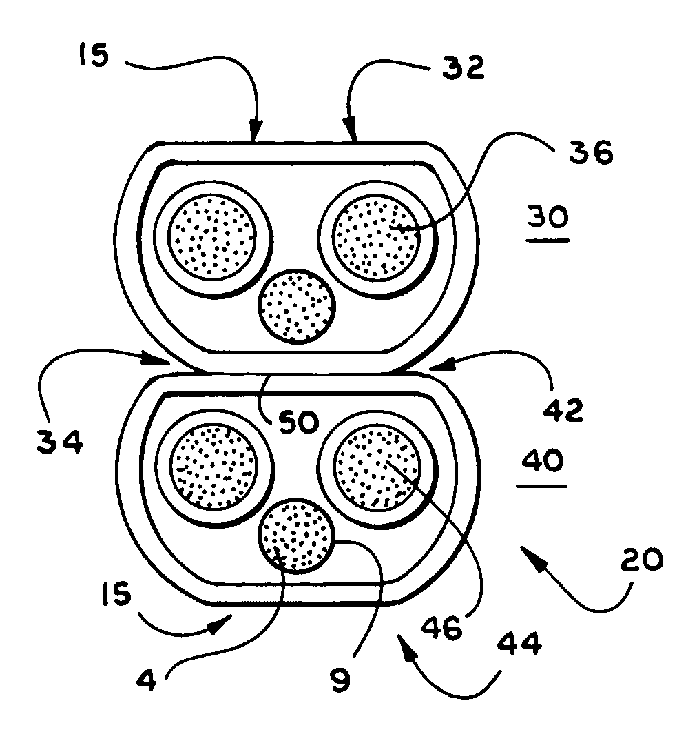
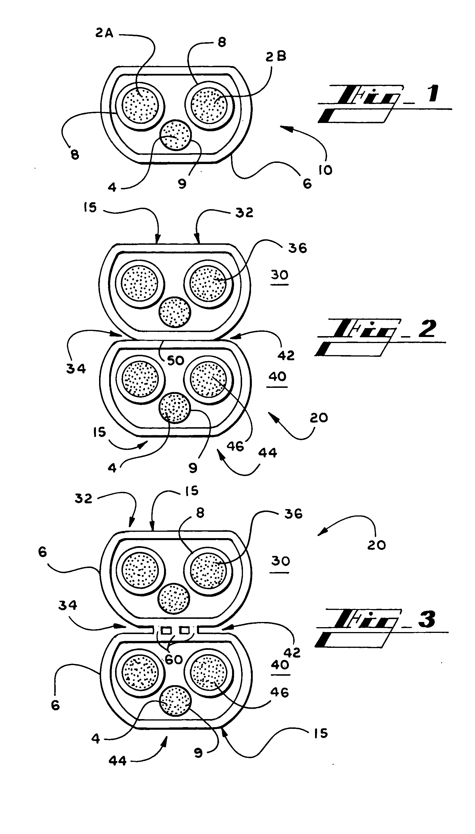
[0030] With continuing reference to FIG. 2, in the present invention, the bottom surface 34 of the first length of NM cable 30 is coupled to the top surface 42 of the second length of NM cable 40 using a cementitious material 50 and at least the top surface 32 of the first length of NM cable 30 and at least the bottom surface 44 of the second length of NM cable 40 are at least partly covered with a lubricant coating 15. In accordance with this embodiment, the cementitious material 50 is applied to either the bottom surface 34 of the first length of NM cable 30 or to the top surface 42 of the second length of NM cable 40. The bottom surface 34 of the first length of NM cable 30 and the top surface 42 of the second length of NM cable 40 are then pressed together to form the coupled building wire 20. It will be appreciated that the cementitious material 50 may be any suitable cement-like substance such as PVC cement or the like.

second embodiment

[0031] With reference to FIG. 3, in the present invention, the bottom surface 34 of the first length of NM cable 30 is coupled to the top surface 42 of the second length of NM cable 40 using glue 60 and at least the top surface 32 of the first length of NM cable 30 and at least the bottom surface 44 of the second length of NM cable 40 are at least partly covered with a lubricant coating 15. In accordance with this embodiment, the glue 60 is applied to either the bottom surface 34 of the first length of NM cable 30 or to the top surface 42 of the second length of NM cable 40 as a non-continuous bead or as a continuous bead. The bottom surface 34 of the first length of NM cable 30 and the top surface 42 of the second length of NM cable 40 are then pressed together to form the coupled building wire 20. It will be appreciated that the glue 60 may be a soft glue or a hard glue.

third embodiment

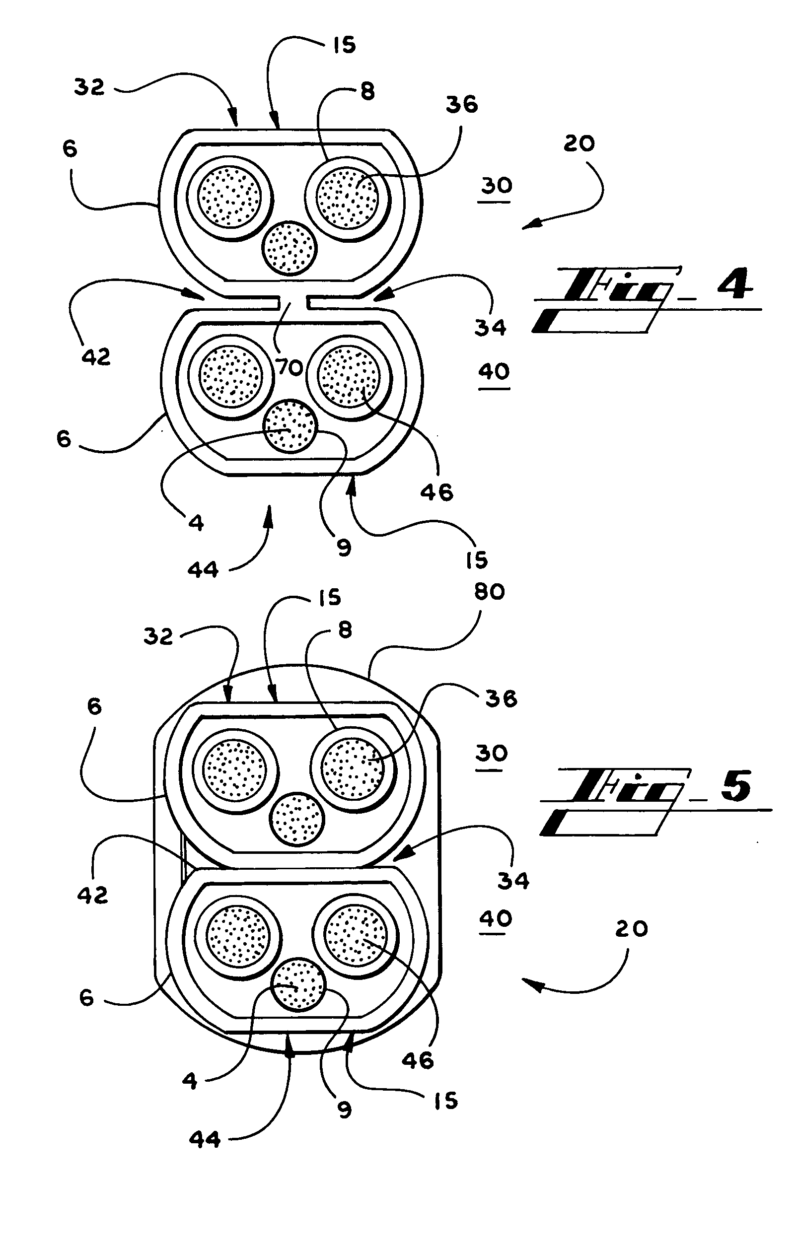
[0032] With reference to FIG. 4, in the present invention, the bottom surface 34 of the first length of NM cable 30 is coupled to the top surface 42 of the second length of NM cable 40 using a webbing material 70 and at least the top surface 32 of the first length of NM cable 30 and at least the bottom surface 44 of the second length of NM cable 40 are at least partly covered with a lubricant coating 15. In accordance with this embodiment, an extrusion machine is employed to apply the webbing material 70 to the bottom surface 34 of the first length of NM cable 30 and the top surface 42 of the second length of NM cable 40. The bottom surface 34 of the first length of NM cable 30 and the top surface 42 of the second length of NM cable 40 are then pressed together to form the coupled building wire 20. It will be appreciated that the webbing material 70 may be any suitable substance such as polypropylene webbing or the like.


PUM

PropertyMeasurementUnit
lengthaaaaaaaaaa
forceaaaaaaaaaa
lengthsaaaaaaaaaa

Abstract

A coupled building wire comprising a first length of non-metallic cable having a top surface and a bottom surface and a second length non-metallic cable having a top surface and a bottom surface, wherein the bottom surface of the first length of non-metallic cable is coupled to the top surface of the second length of non-metallic cable, and wherein at least the top surface of the first length of non-metallic cable and at least the bottom surface of the second length of non-metallic cable are at least partly covered with a lubricant coating. The first length of non-metallic cable comprises at least one circuit conductor having a first gauge. The second length of non-metallic cable comprises at least one circuit conductor having a second gauge. The first gauge of the at least one circuit conductor of the first length of non-metallic cable may be substantially equal or unequal to the second gauge of the at least one circuit conductor of the second length of non-metallic cable.

Description

RELATED APPLICATIONS [0001] This application claims the benefit of priority of U.S. provisional application Ser. No. 60 / 544,294, filed Feb. 12, 2004, which is relied on and incorporated herein by reference.FIELD OF THE INVENTION [0002] The present invention relates generally to electrical wire and cable. More specifically, the present invention relates to coupled building wire comprising more than one length of non-metallic sheathed cable, wherein the lengths of cable are coupled and covered with a lubricant coating so that an electrician can pull more than one length of cable into a structure at a time using less force than that required by conventional building wire. BACKGROUND OF THE INVENTION [0003] Non-metallic (“NM”) sheathed cable is suitable for use in concealed or exposed, dry, protected areas (e.g., inside stud walls and on the sides of joists) and is commonly used to provide electrical power throughout homes built in the United States. NM cable is installed during the con...

Claims


Application Information

Patent Timeline
Patent Type & Authority Applications(United States)
IPC IPC(8): G02B6/00H01B7/18H02G3/02
CPCH01B7/1885
Inventor CARLSON, JOHN R.MERCIER, CHARLES D.DIXON, MARK D.KUMMER, RANDY D.ARMSTRONG, JOHN W.
Owner SOUTHWIRE CO LLC
Why Eureka
Try Eureka