
Optical disk for high resolution and general video recording, optical disk reproduction apparatus, optical disk recording apparatus, and reproduction control information generation apparatus

a high-resolution, optical disk technology, applied in the direction of video signal spatial resolution conversion, television system, selective content distribution, etc., can solve the problems of normal pictures cannot be output, and conventional optical disk for high-quality picture recording is not compatible with a standard video reproduction apparatus

Inactive Publication Date: 2005-08-18
PANASONIC CORP
View PDF23 Cites 63 Cited by
  • Summary
  • Abstract
  • Description
  • Claims
  • Application Information

AI Technical Summary

Problems solved by technology

First, a first problem of the conventional system will be described.
When a conventional optical disk for high quality picture recording is reproduced by a standard reproduction apparatus, normal pictures cannot be output.
In other words, the conventional optical disk for high quality picture recording is not compatible with a standard video reproduction apparatus.
Then, a second problem of the conventional system is regarding a reproduction control system.
Accordingly, in order to connect two streams of a high resolution signal seamlessly, i.e., without stopping the movement of the video, a complicated system is required.

Method used


Image

  • Optical disk for high resolution and general video recording, optical disk reproduction apparatus, optical disk recording apparatus, and reproduction control information generation apparatus
  • Optical disk for high resolution and general video recording, optical disk reproduction apparatus, optical disk recording apparatus, and reproduction control information generation apparatus
  • Optical disk for high resolution and general video recording, optical disk reproduction apparatus, optical disk recording apparatus, and reproduction control information generation apparatus

Examples


example 1

[0114] (720P / 480P Hierarchical Recording and Reproduction System)

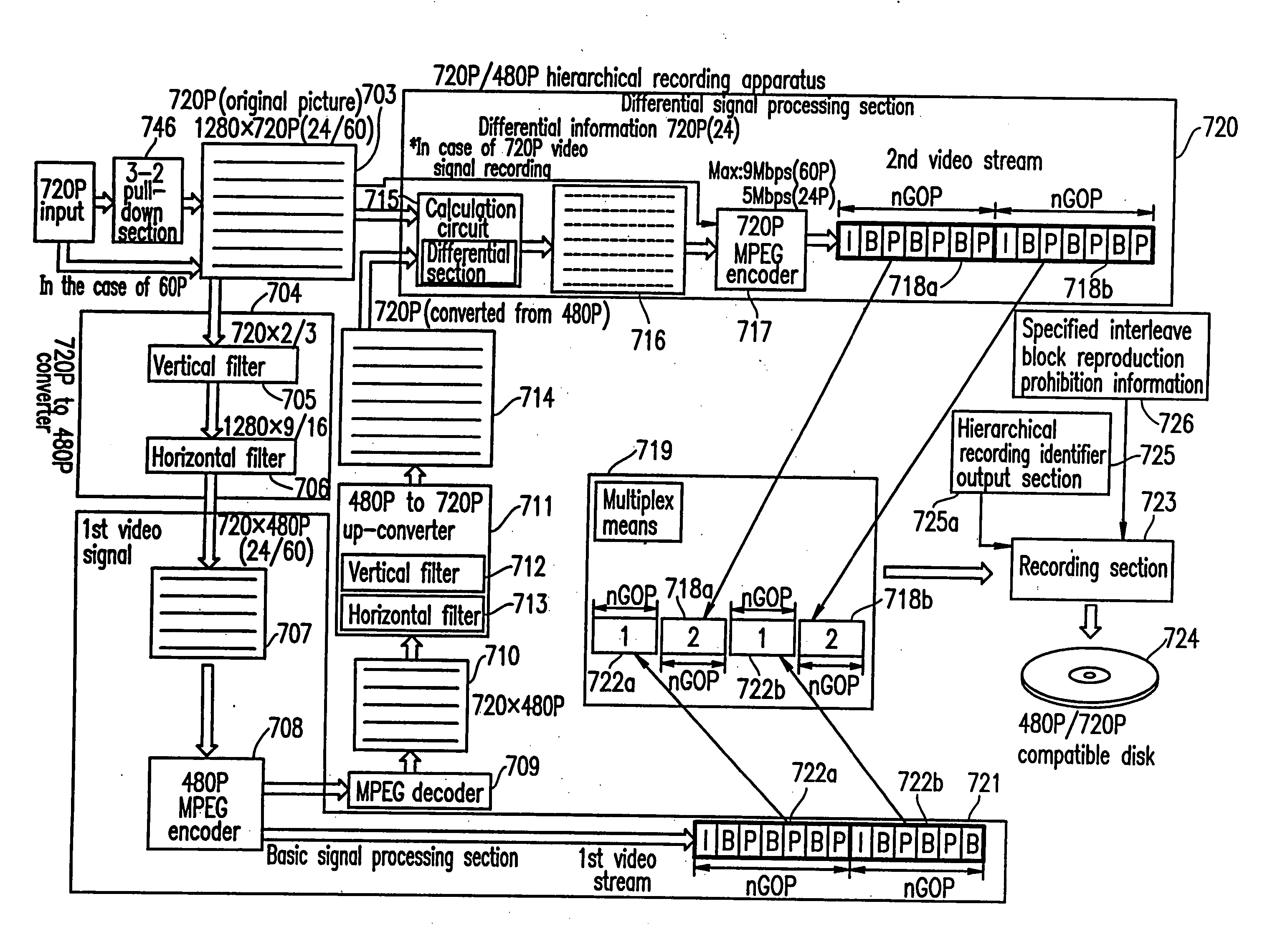
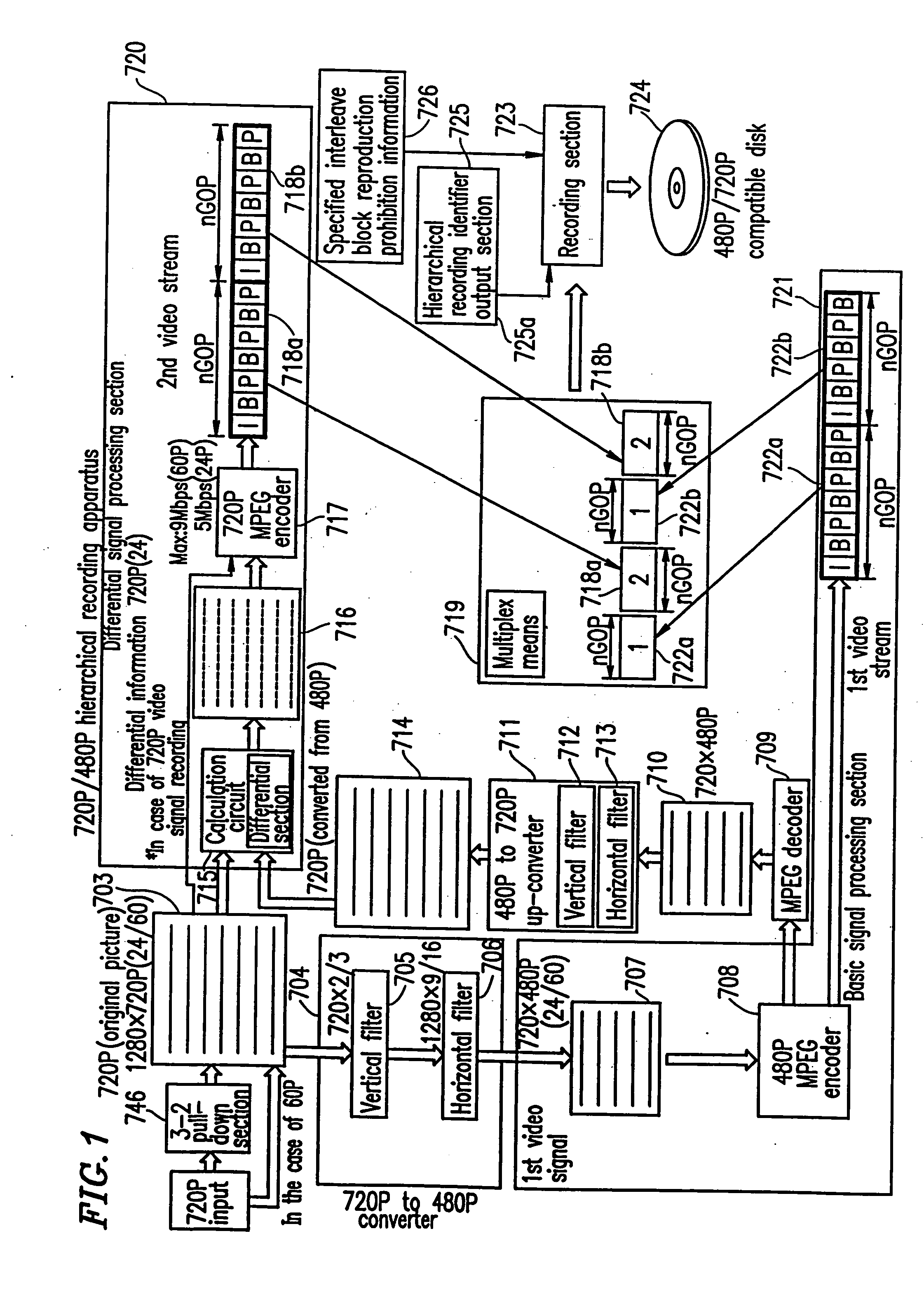
[0115] With reference to FIG. 1, a specific hierarchical recording apparatus for handling two hierarchical layers of 720P and 480P will be described. Later, a method for recording a HDTV signal in a hierarchical manner in the state where the HDTV signal is divided into a plurality of signals will be described, with reference to FIG. 20.

[0116] In the case of a movie signal, specifically, an original 720P video signal of 60 frames per second, the signal is input and then has extra frames deleted by a 3-2 pull-down section 746. As a result, a 720P (24P) signal 703 of 24 frames per second is obtained. In the case of a normal 60P video signal, the 3-2 pull-down section is bypassed. Herein, 60P refers to 60 frames per second. The 720P video signal 703 having 1280×720 pixels is processed by a 720P / 480P down-converter 704 as follows. First, the number of vertical lines is reduced to 720×⅔=480 by a vertical filter 705. Then, ...

example 2

[0226] In the first example, an example of application of a system for reproducing a plurality of streams in synchronization according to the present invention is described in detail. In a second example, this system is applied to a reproduction control system for reproducing two streams seamlessly. In the case of recording an MPEG signal, editing is conventionally performed on a GOP-by-GOP basis in general, and it is difficult by conventional methods to perform editing on a frame-by-frame basis. By using an MSS system according to the present invention, substantial frame-based editing is realized.

[0227] It is important to synchronize the timing of the video signal and the audio signal at the point of connection. Specific synchronization systems will be described in third through ninth examples.

[0228] The reproduction control system according to the present invention can be applied as follows to connect two streams while switching the two streams on a frame-by-frame basis seamless...

example 3

[0276] The MADM system according to the present invention simultaneously reproduce a plurality of streams. Synchronization systems are important.

[0277] In the first example, recording and reproduction of high resolution video signals such as 480P and 720P signals are described. In the second example, basic AV synchronization systems for reproduction control using virtual frame-based editing are described. In the third through ninth examples, various methods of synchronization will be described in more detail.

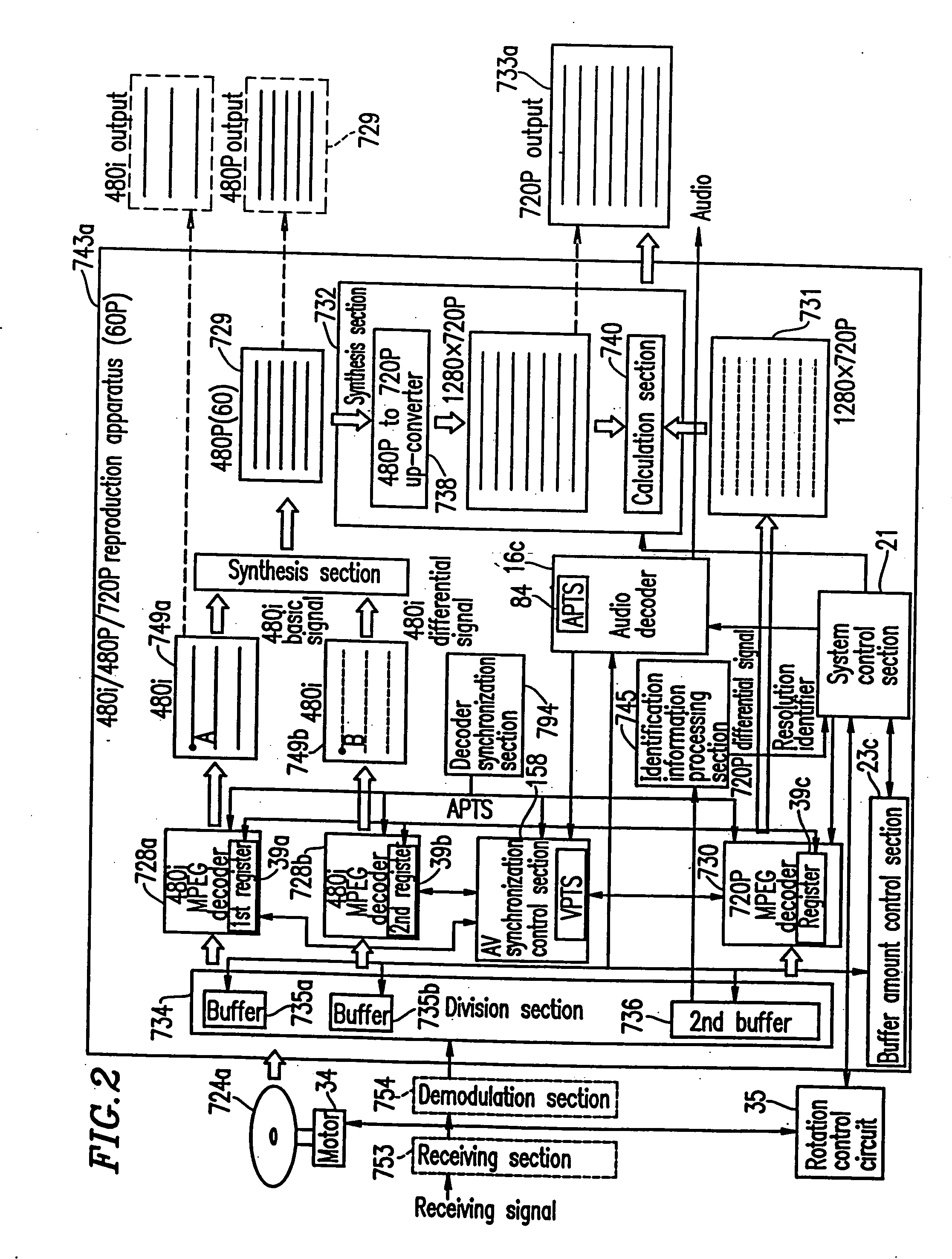
[0278] In the third example, an operation of a reproduction apparatus for reading data from an optical disk having three compression video signals to be reproduced simultaneously, and extending and reproducing the three compression video signals simultaneously by an AV synchronization system will be described.

[0279]FIG. 37 shows a data structure of an optical disk used in the optical disk reproduction apparatus in the third example.

[0280] Video signals A, B and C are MPEG-co...


PUM


Abstract

The present invention has an objective of realizing compatibility of an optical disk having a high resolution video signal recorded thereon and a system for reproducing the optical disk, with a conventional system for producing a standard resolution video signal. A high resolution video signal is divided by video division means into a main signal and a sub signal, and the main signal and the sub signal are MPEG-encoded. The stream of the main signal and the stream of the sub signal are divided into 1 GOP or more of frames. First interleave blocks 54 each including 1 GOP or more of the stream of the main signal and second interleave blocks 55 each including 1 GOP or more of the stream of the sub signal are recorded on an optical disk 1. A high resolution reproduction apparatus reproduces both the first and second interleave blocks to obtain a high resolution video output. A non-high quality picture reproduction apparatus reproduces only the first or second interleave blocks to obtain a standard resolution video output.

Description

TECHNICAL FIELD [0001] The present invention relates to an optical disk having high quality picture or standard picture recorded thereon, and a recording and reproduction apparatus for such an optical disk. BACKGROUND ART [0002] For an optical disk having high quality picture recorded thereon and a reproduction apparatus for such an optical disk, systems referred to as 480P and 720P for recording progressive data have conventionally been studied A conventionally known reproduction control system for an optical disk uses one MPEG decoder. [0003] First, a first problem of the conventional system will be described. When a conventional optical disk for high quality picture recording is reproduced by a standard reproduction apparatus, normal pictures cannot be output. The optical disk for high quality picture recording can only be reproduced by a high quality picture reproduction apparatus. Accordingly, there is a need to produce two types of optical disks having the same contents. In ot...

Claims


Application Information

Patent Timeline
Patent Type & Authority Applications(United States)
IPC IPC(8): H04N5/04H04N5/44H04N5/45H04N5/46H04N5/765H04N5/775H04N5/85H04N7/50H04N9/79H04N9/804H04N9/806H04N9/82H04N9/877H04N13/239H04N21/43
CPCG11B2020/10953H04N21/4325H04N5/4401H04N5/45H04N5/46H04N5/765H04N5/775H04N5/85H04N7/012H04N7/0122H04N9/7921H04N9/8042H04N9/8063H04N9/8205H04N9/8227H04N9/877H04N13/0003H04N13/0037H04N13/0048H04N13/0051H04N13/0055H04N13/0059H04N13/0066H04N13/0239H04N13/0438H04N13/0456H04N13/0459H04N13/0497H04N2013/0085H04N19/597H04N21/42646H04N21/4307H04N5/04H04N13/341H04N13/167H04N13/194H04N13/189H04N13/161H04N13/363H04N13/10H04N13/15H04N13/239H04N13/361H04N13/178H04N13/398H04N21/426H04N21/43072
Inventor OSHIMA, MITSUAKIKITAURA, HIROMUFUKUDA, HIDEKIISHIHARA, HIDESHI
Owner PANASONIC CORP
Learn More