Configuration display apparatus for computer, computer configuration display method, and computer configuration display program

Inactive Publication Date: 2005-08-18
FUJITSU LTD
View PDF14 Cites 47 Cited by
  • Summary
  • Abstract
  • Description
  • Claims
  • Application Information

AI Technical Summary

Benefits of technology

[0010] The present invention has been devised in order to solve the above-described problems, and it is an object of the present invention to provide a computer configuration display apparatus, a computer configuration di

Problems solved by technology

It may take time to specify a cause of the state, for example, in the case in which the physical configuration or the logical configuration of the computer is complicated.
In addition, it may be difficult to judge which of the phy

Method used


Image

  • Configuration display apparatus for computer, computer configuration display method, and computer configuration display program
  • Configuration display apparatus for computer, computer configuration display method, and computer configuration display program
  • Configuration display apparatus for computer, computer configuration display method, and computer configuration display program

Examples


first embodiment

(First Embodiment)

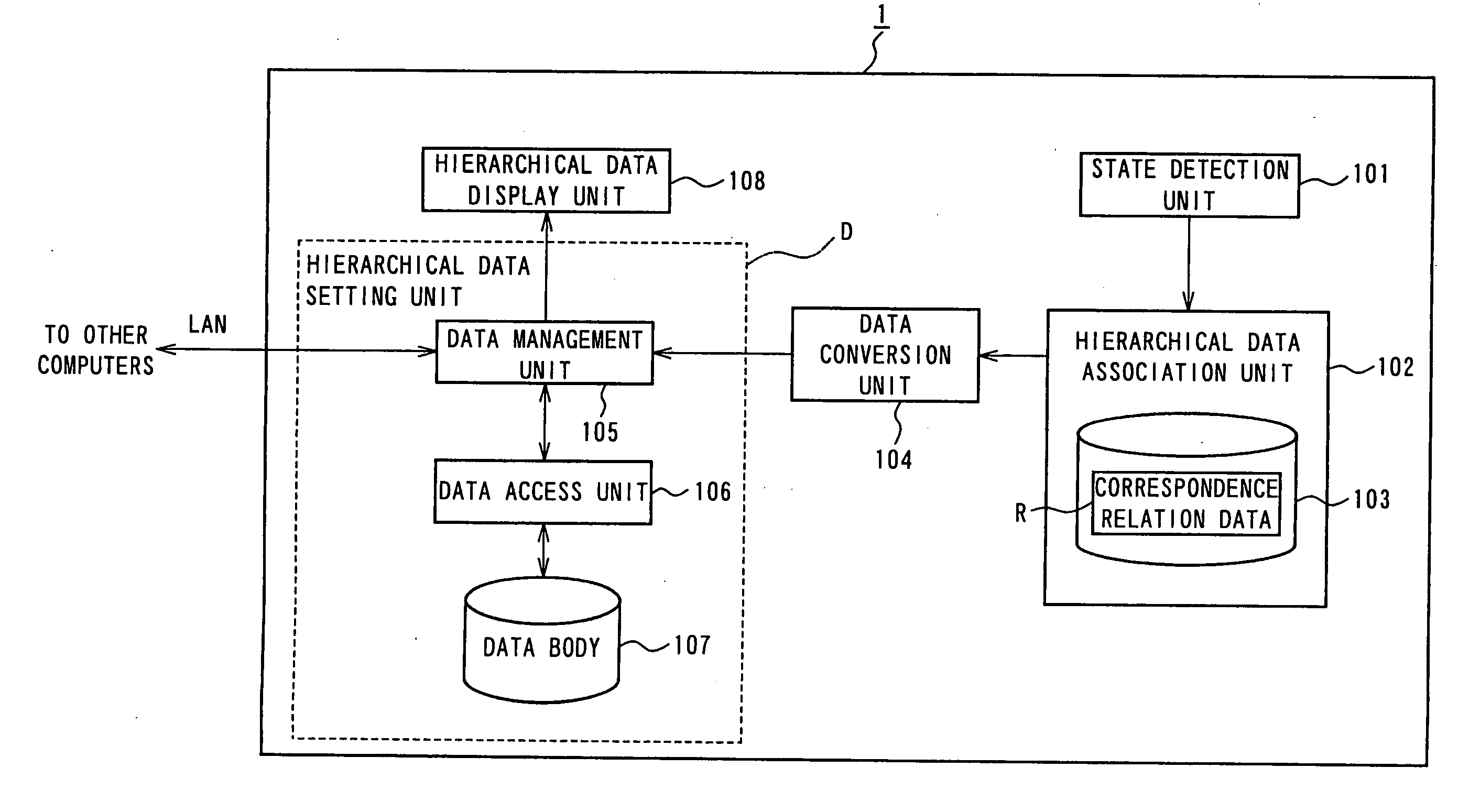
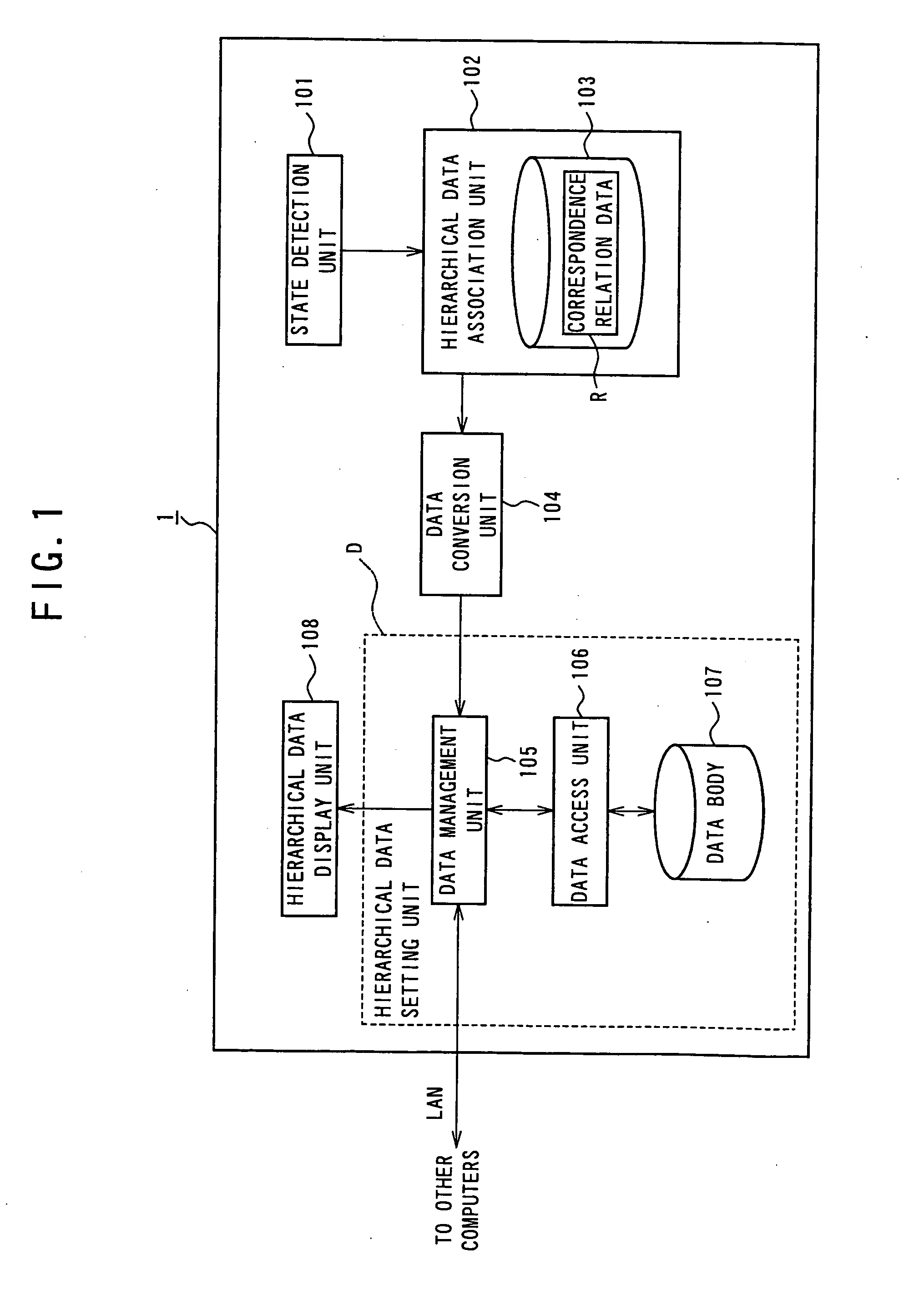
[0053]FIG. 1 is a functional block diagram for explaining a structure of a computer configuration display apparatus according to an embodiment of the present invention.

[0054] A computer configuration display apparatus 1 according to the present embodiment is an apparatus that, in order to perform management of a computer having plural physical components and logical components, performs display concerning components of the computer. Here, the computer configuration display apparatus 1 is arranged inside the computer.

[0055] The computer configuration display apparatus 1 includes a state detection unit 101, a hierarchical data association unit 102, a data conversion unit 104, a hierarchical data setting unit D, a hierarchical data display unit 108, a not-shown storage area, and a not-shown CPU.

[0056] The hierarchical data association unit 102 plays a role of creating various data concerning a computer to be managed. For example, the hierarchical data association u...

second embodiment

(Second Embodiment)

[0113] Subsequently, a second embodiment of the invention will be explained. This embodiment is a modification of the first embodiment and is different from the first embodiment in processing at the time when a change in a state occurs in a predetermined physical component or a predetermined logical component. In the following explanation, components having the identical functions as the components already described in the first embodiment are denoted by the identical reference numerals and signs and explanations of the components are omitted.

[0114]FIG. 15A is a diagram for explaining an example of screen display of a physical hierarchical data and FIG. 15B is a diagram showing a hierarchical structure of the physical hierarchical data. In the physical hierarchical data shown in the figure, a cooling fan 308 and a power supply 309 are included in the same hierarchy as the system board 305 of the physical hierarchical data shown in FIGS. 3A and 3B in the first emb...


PUM


Abstract

The present invention provides a computer configuration display apparatus, a computer configuration display method, and a computer configuration display program that can contribute to reduction of a burden on a system administrator who performs management concerning physical components and logical components of a computer. The computer configuration display apparatus includes: a hierarchical data association unit that associates physical hierarchical data, which defines plural physical components of a computer as plural hierarchical data according to a predetermined physical segmentation, and logical hierarchical data, which defines plural logical components of the computer as plural hierarchical data according to a predetermined logical segmentation, with each other; a hierarchical data setting unit that sets the associated physical hierarchical data and logical hierarchical data; and a hierarchical data display unit that displays the physical hierarchical data and the logical hierarchical data set in the hierarchical data setting unit.

Description

BACKGROUND OF THE INVENTION [0001] 1. Field of the Invention [0002] The present invention relates to a computer configuration display apparatus, a computer configuration display method, and a computer configuration display program. [0003] 2. Related Background Art [0004] Conventionally, management work for a computer has problems as described below (e.g., see pages 5 to 8 and FIG. 1 of Japanese Patent Application Laid-Open No. 2001-282632, pages 2 to 4 and FIG. 1 of Japanese Patent Application Laid-Open No. 11-212826, and pages 4 to 11 and FIG. 1 of Japanese Patent Application Laid-Open No. 10-294731). [0005] In a computer system that is required to operate stably for 24 hours in 365 days, in the event that a physical component of a computer or a logical component from the viewpoint of an OS installed in the computer has fallen into a state that adversely affects the computer (an error or the like), a cause for the component having fallen into the state has to be specified and remov...

Claims


Application Information

Patent Timeline
IPC IPC(8): G06F15/00G06F15/177
CPCG06F15/177G06F11/32
Inventor UCHIDA, HIROHISAHOSHI, DAISUKEMATSUMURA, YASUHIRO
Owner FUJITSU LTD
Why Eureka
Try Eureka