Strip planarity measuring method and apparatus

Inactive Publication Date: 2005-08-25
BWG BERGWERK & WALZWERK MASCHINENBAU GMBH
View PDF7 Cites 2 Cited by
  • Summary
  • Abstract
  • Description
  • Claims
  • Application Information

AI Technical Summary

Benefits of technology

[0020] According to a preferred embodiment of the invention it is however provided that the part measuring heads are formed as beam sensors and are supported in the beam end regions on force transmitters. The force transmitters are formed as piezo quartzes. The beam sensors can be disposed in a straight line or obliquely with respect to the roller axis. The oblique arrangement owes a wave-shaped progression of the beam sensor. Into the part measuring head encircling motion gap or clearance a permanently elastic adhesive and/or a seal or in the case of a circular embodiment of the measuring head an O-ring can be inserted. Expediently the measuring h

Problems solved by technology

In fact however there is a danger that the magnitude of the force shunt will change in operation, e.g. due to temperature changes, and the

Method used


Image

  • Strip planarity measuring method and apparatus
  • Strip planarity measuring method and apparatus
  • Strip planarity measuring method and apparatus

Examples


Example

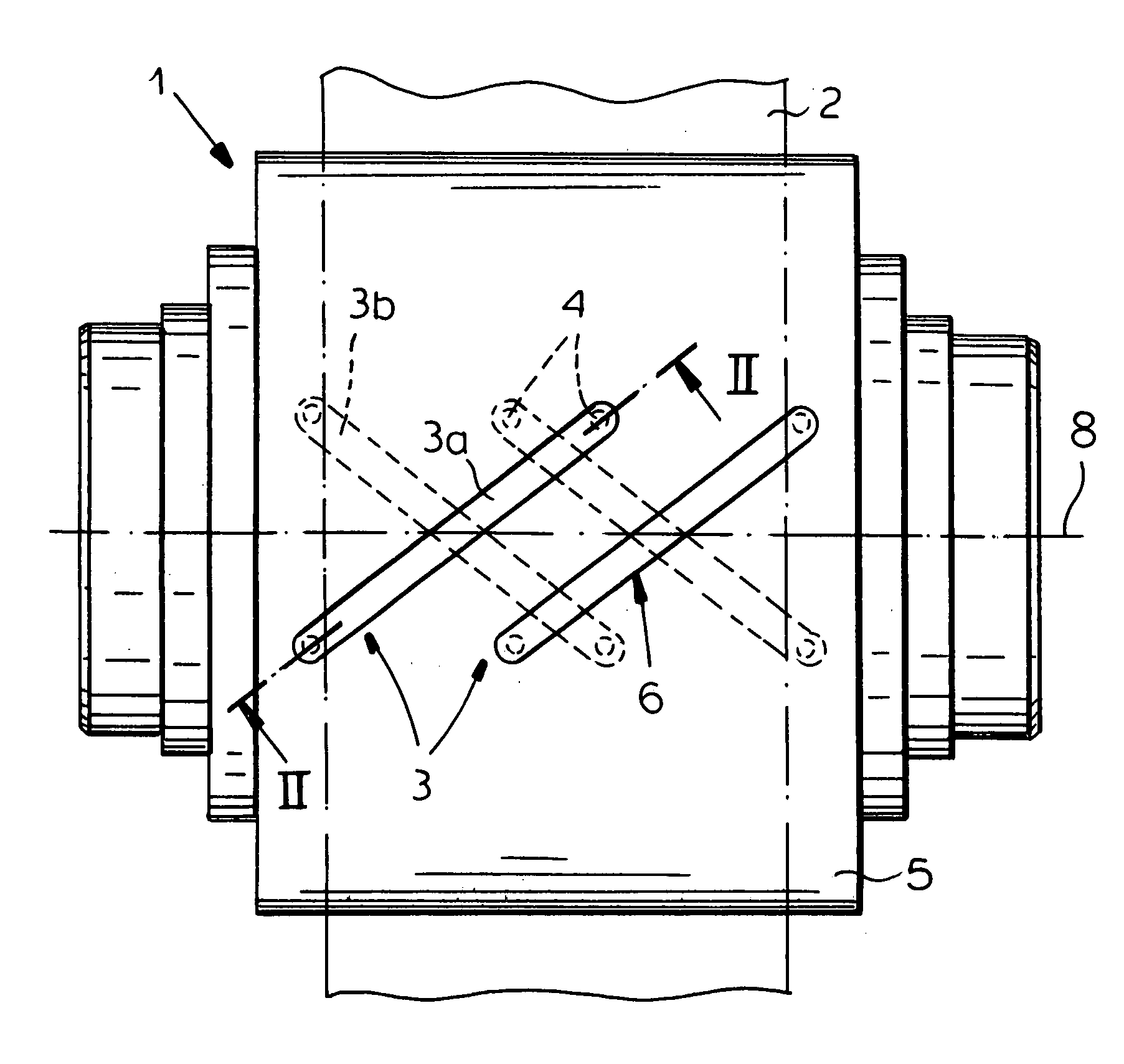
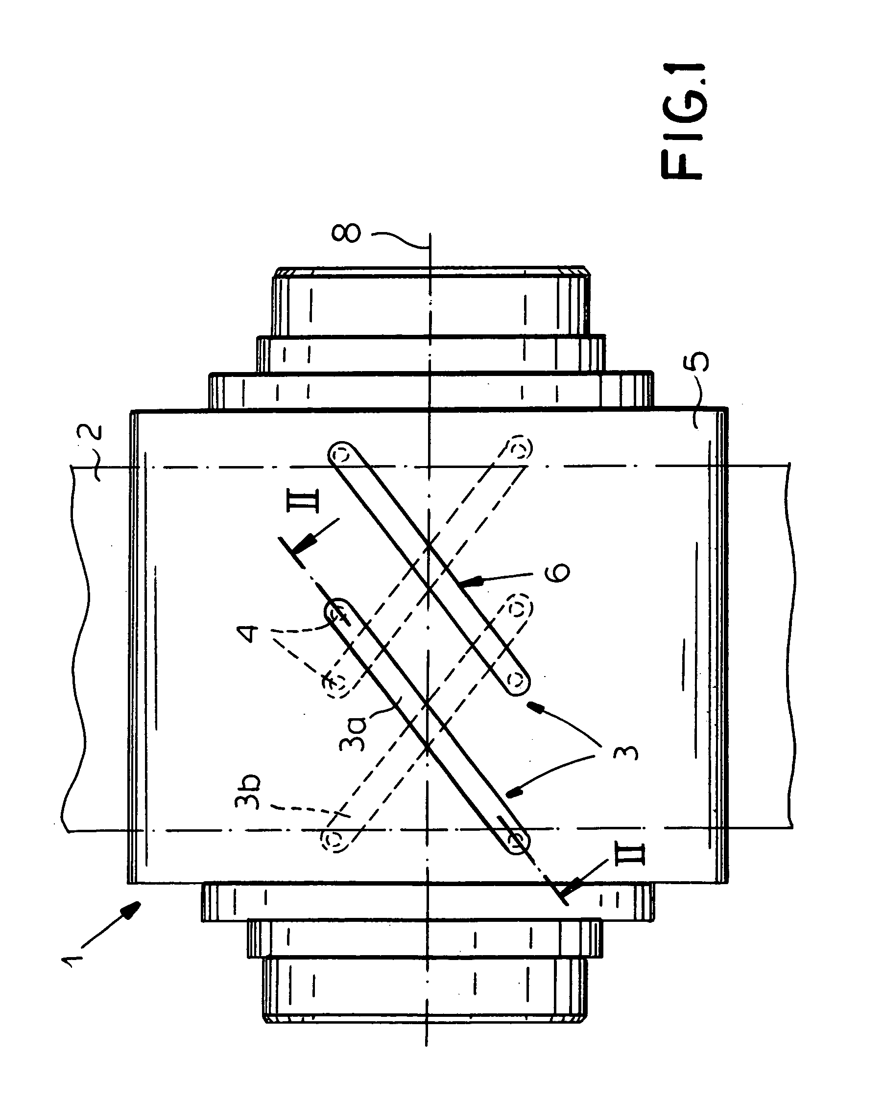
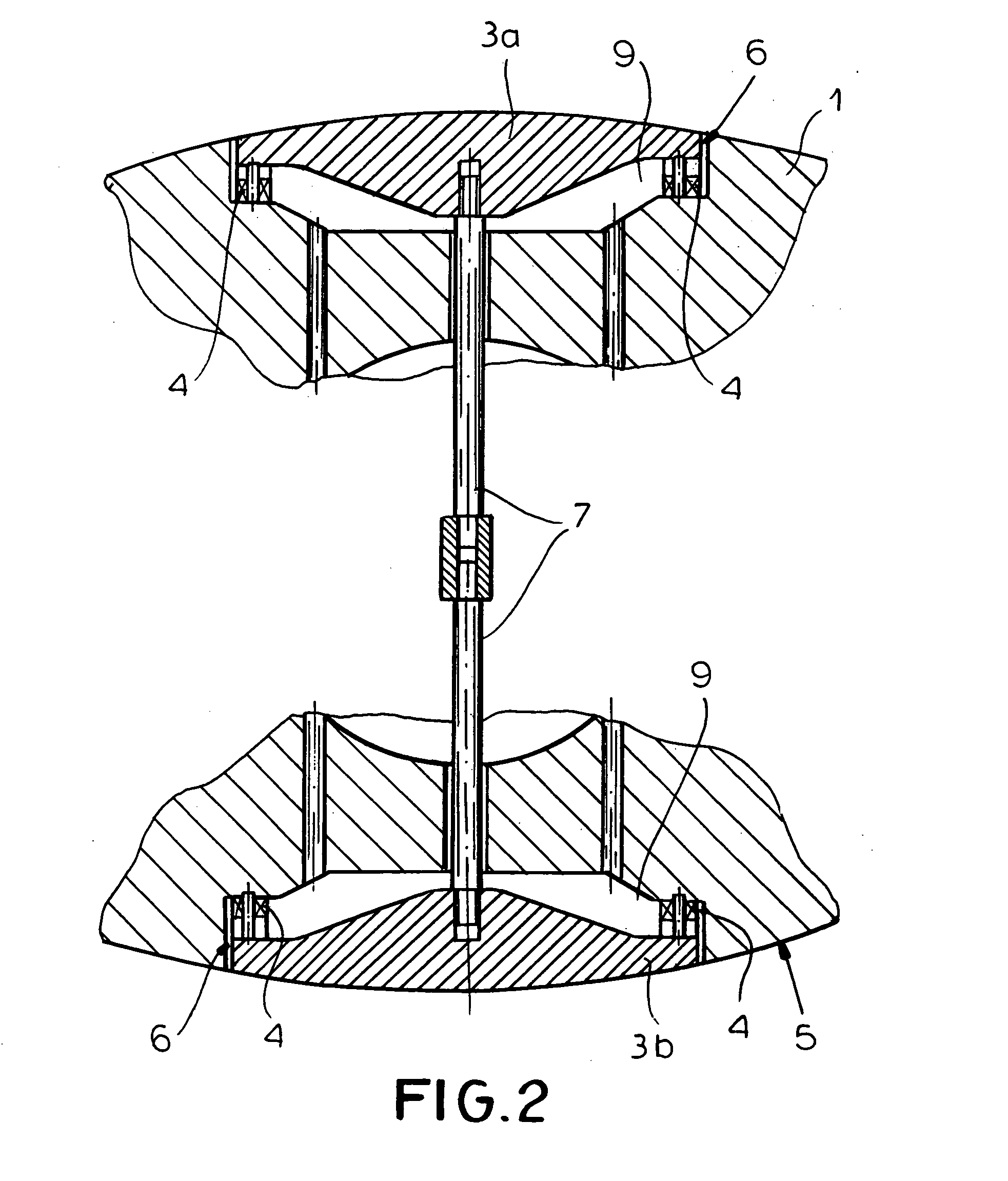
[0028] FIGS. 1 to 4 illustrate surface evenness (planarity) sensor rollers 1 for the purpose of determining surface evenness errors, defects or irregularities, in strip 2 and particularly steel strip and other metal strip as the strip 2 passes for example through strip processing lines or rolling mill trains.

[0029] This surface evenness sensor roller comprises at least one measuring head or unit 3 with two part measuring heads integrated in the roller and respectively offset by 180° in the roller mantel or surface and supported on two force transmitters 4. The heads are further separated from the roller mantel 5 by means of a circumferential motion gap (peripheral clearance) 6 and braced with respect to one another by means of at least one tie rod 7.

[0030] In the course of a measurement of the band tensile stress distribution over the strip width the strip 2 is subjected to tensile stress over its whole strip width and wraps around the surface evenness sensor roller 1 with a prede...


PUM

PropertyMeasurementUnit
Angleaaaaaaaaaa
Weightaaaaaaaaaa
Angleaaaaaaaaaa

Abstract

A method and a surface evenness measuring roller for determining surface evenness measurement errors in steel and metal band comprising at least one measuring head having part measuring heads which part measuring heads are integrated respectively offset by 180° into the roller mantel and supported on two force transmitters and are further separated from the roller mantle by means of a circumferential motion gap and are braced with respect to one another by means of at least one tie rod wherein in the course of a measurement of the band tensile stress distribution over the whole band width the band with band is subject to tension over its whole band width wraps around the surface evenness measuring roller with a predetermined arc of contact and thereby exerts pressing forces onto the surface evenness measuring roller from which pressing forces can be determined the band tension distribution.

Description

FIELD OF THE INVENTION [0001] My present invention relates to a method of determining surface evenness errors (defects or irregularity in strip planarity) and particularly steel and metal strip as the strip passes through strip processing lines or mill trains. BACKGROUND OF THE INVENTION [0002] Strip planarity measurement is known, for example, from EP 1 369 186 A2 and copending application Ser. No. 10 / 417,808 filed 17 Apr. 2003 (U.S. 2003 / 0236637 A1) which uses a surface evenness measuring roller with at least one integrated beam sensor. The beam sensor extends longitudinally in a wavy or straight line over the length of the roller for the purpose of determining tensile forces acting on said roller from the strip. The strip is partially wrapped around the sensor roller wherein during the determining of the tensile force the beam sensor with its starting region and its end region is at least occasionally within an arc of contact that is formed by the band. The sensor beam is support...

Claims


Application Information

Patent Timeline
IPC IPC(8): B21B37/28B21B38/02G01L5/04
CPCB21B37/28G01L5/045B21B38/02B01D46/0027A01M1/14A61L9/205B01J35/004B01D53/88B01D46/4254B01D46/0045B01D46/44B01D2255/802B01D2259/804
Inventor NOE, ANDREAS
Owner BWG BERGWERK & WALZWERK MASCHINENBAU GMBH
Why Eureka
Try Eureka