Self-contained airborne smart weapon umbilical control cable

Active Publication Date: 2005-08-25
RAYTHEON CO
View PDF9 Cites 33 Cited by
  • Summary
  • Abstract
  • Description
  • Claims
  • Application Information

AI Technical Summary

Benefits of technology

[0009] According to one aspect of the invention, an umbilical cable is provided for delivering electrical signals between an aircraft and a smart weapon carried by the aircraft. The umbilical cable includes cabling comprising a plurality of conductive wires, a first connector provided on one end of the cabling and configured to connect to the aircraft, and a second connector provided on the other end of the cabling and configured to connect to the smart weapon. The umbilical cable further includes an interface circuit electrically coupled between the first connector and the second connector via the plurality of conductive wires. The interface circuit is configured to receive via the first connector a non-standard combination of signals comprising at least one of data signals, control signals and power signals not receivable directly by the smart weapon to carry out operations. Moreover, the interface circuit is configured to convert the non-standard combination of signals to a set of signals receivable by the smart weapon to carry out operations, and to provide the set of receivable signals to the smart weapon via the second connector.
[0010] According to another aspect of the invention, provided is a method of loading operation data into a smart weapon configured to b

Problems solved by technology

Some smart weapons do not fit cleanly in the above typology.
Unfortunately, there is a significant number of older aircraft that are still in use today but are not properly equipped to handle smart weapons.
For example, such aircraft may not include the MIL-STD-1553 databus and thus are unable to communicate with a smart weapon such as the JDAM.
Replacing the older aircraft, which are otherwise perfectly functional, is e

Method used


Image

  • Self-contained airborne smart weapon umbilical control cable
  • Self-contained airborne smart weapon umbilical control cable
  • Self-contained airborne smart weapon umbilical control cable

Examples


Embodiment Construction

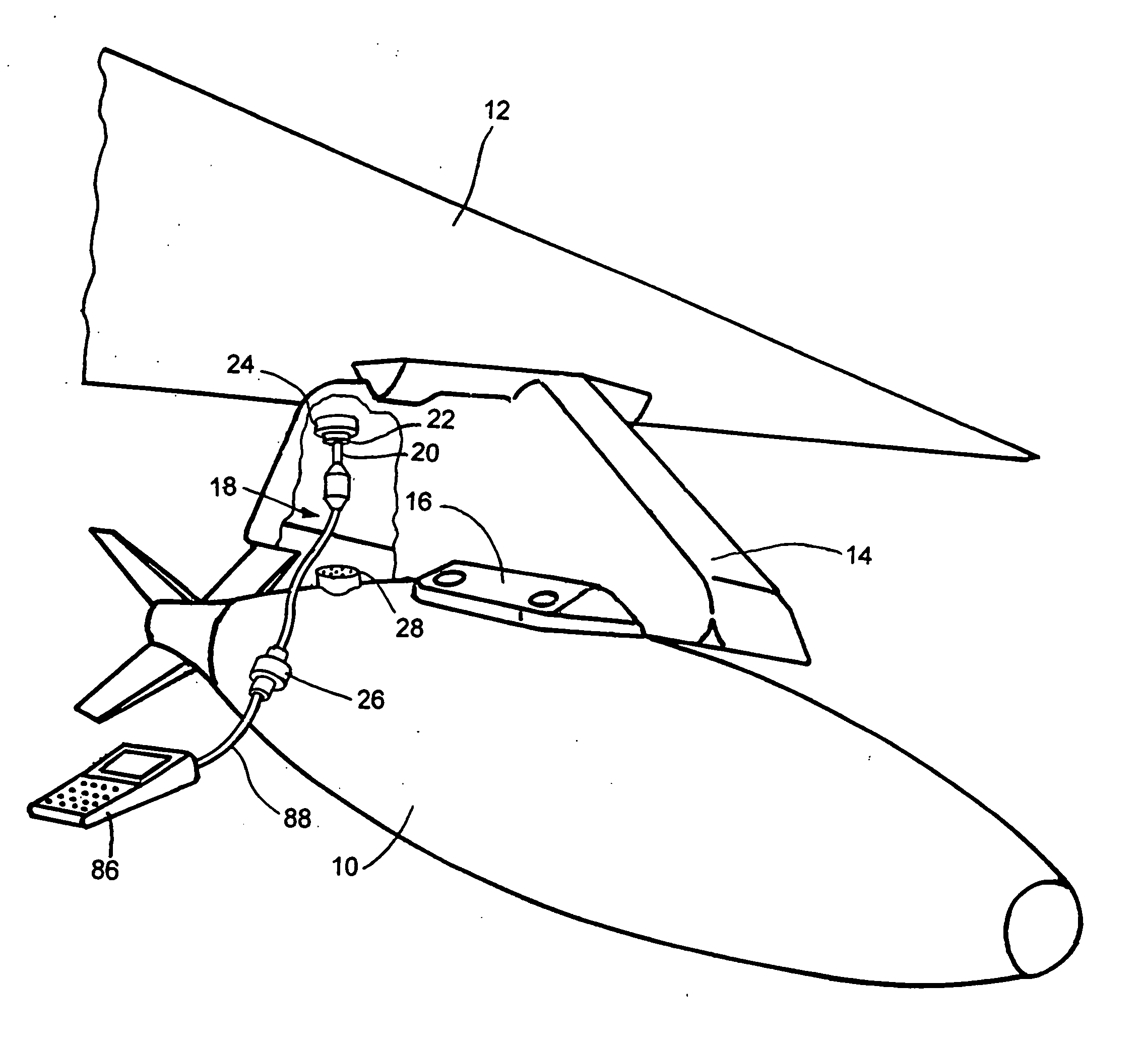
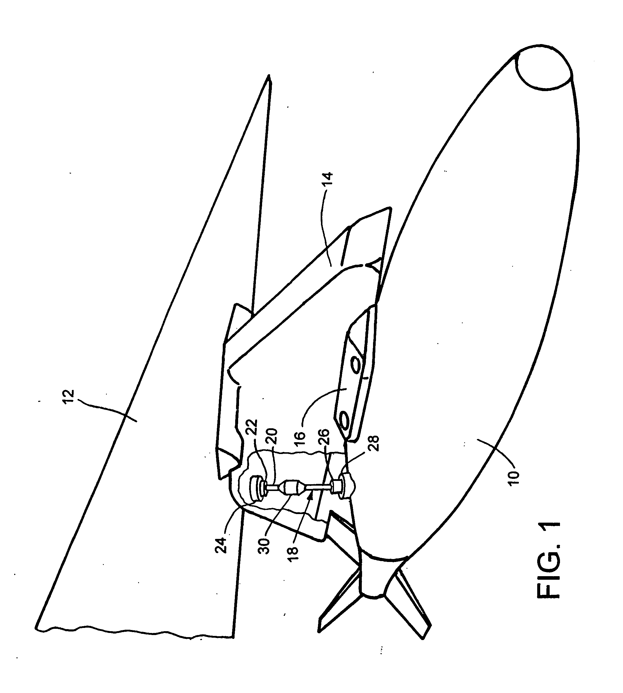
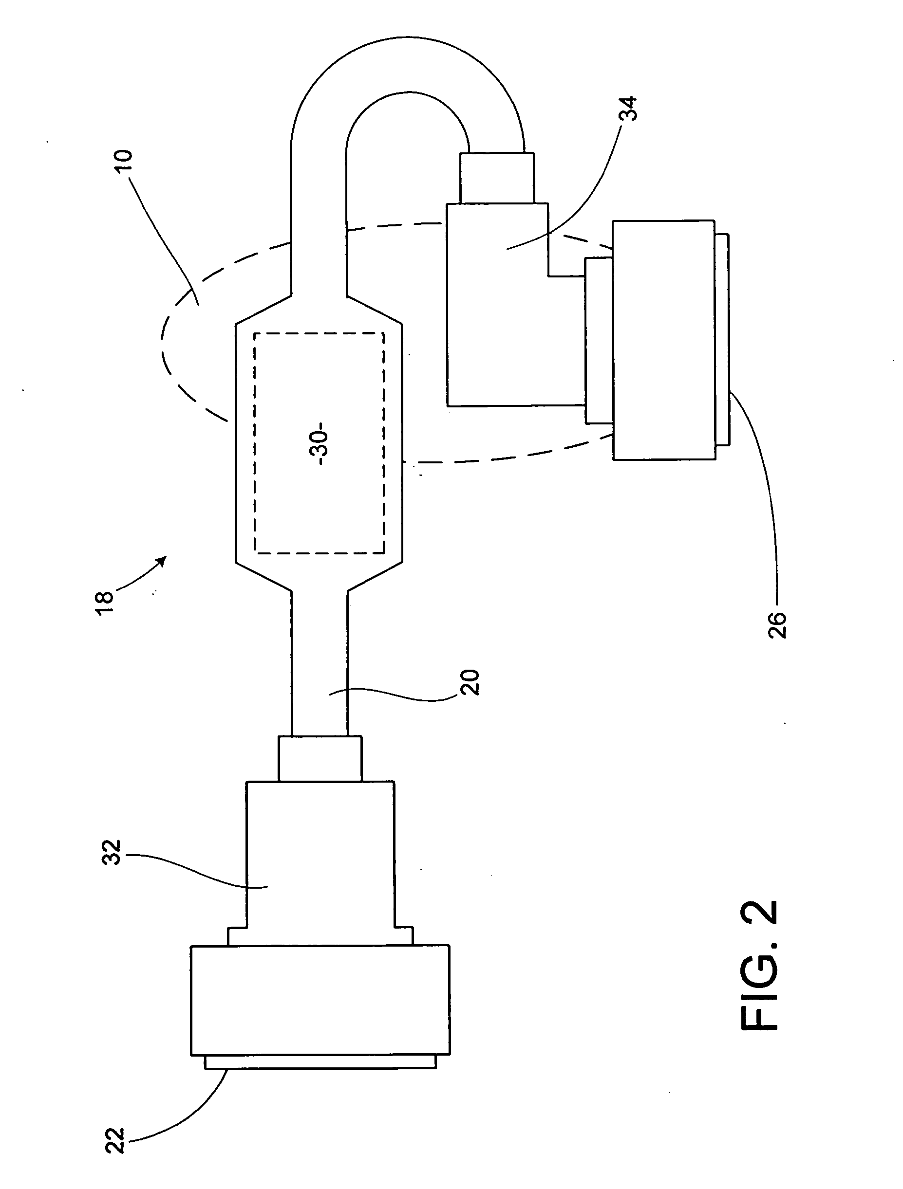
[0019] The present invention will now be described in detail with reference to the drawings, in which like reference numerals are used to refer to like elements throughout.

[0020] The present invention relates to an umbilical cable for connecting a smart weapon to an aircraft that is not otherwise equipped to handle the smart weapon. Referring initially to FIG. 1, a smart weapon 10 is shown mounted to the wing 12 of an aircraft. As is typical, the wing 12 includes one or more pylons 14 secured to the underside of the wing 12. Each pylon typically supports a bomb rack 16 used to secure various types of weapons.

[0021] In accordance with the present invention, the weapon 10 is a smart weapon, i.e., one capable of altering its trajectory in flight to seek, or home on, its target. In an exemplary embodiment described herein, the smart weapon 10 is a JDAM or other MIL-STD-1760 type smart weapon. However, it will be appreciated that the smart weapon 10 could be any other type of smart wea...


PUM


Abstract

An umbilical cable for delivering electrical signals between an aircraft and a smart weapon carried by the aircraft. The umbilical cable includes cabling comprising a plurality of conductive wires, a first connector provided on one end of the cabling and configured to connect to the aircraft, and a second connector provided on the other end of the cabling and configured to connect to the smart weapon. The umbilical cable further includes an interface circuit electrically coupled between the first connector and the second connector via the plurality of conductive wires. The interface circuit is configured to receive via the first connector a non-standard combination of signals comprising at least one of data signals, control signals and power signals not receivable directly by the smart weapon to carry out operations. Moreover, the interface circuit is configured to convert the non-standard combination of signals to a set of signals receivable by the smart weapon to carry out operations, and to provide the set of receivable signals to the smart weapon via the second connector.

Description

TECHNICAL FIELD [0001] The present invention relates generally to aircraft and aircraft weaponry. More specifically, the present invention relates to an umbilical cable for connecting a smart weapon to an aircraft not otherwise equipped to handle the smart weapon. BACKGROUND OF THE INVENTION [0002]“Smart” weapons, also referred to as precision guided munitions (PGMs), alter their trajectories in flight to seek, or home on, their targets. Unlike conventional ballistic munitions, their accuracy does not normally diminish as range increases. Generally speaking, smart weapons are divided into four categories, according to their method of homing: command guidance, active, semiactive, and passive. Munitions using command guidance are steered to the target by a remote system or operator that performs all target acquisition, tracking, and guidance functions. Active systems home on their targets using emissions transmitted by the munition itself. Semiactive smart weapons home on energy bound...

Claims


Application Information

Patent Timeline
IPC IPC(8): F41G7/00F42C15/40F42C17/04
CPCF41G7/007F42C17/04F42C15/40F41G7/001
Inventor MCMAHON, ROY PATRICK
Owner RAYTHEON CO
Why Eureka
Try Eureka