Fuel injection control apparatus for internal combustion engine

a technology of control apparatus and internal combustion engine, which is applied in the direction of electric control, combustion air/fuel air treatment, machines/engines, etc., can solve the problems of unadjusted problem and non-uniform distribution of fuel injected by direct injector in the combustion chamber, and achieve the effect of suppressing the hampering of engine combustion

Inactive Publication Date: 2005-08-25
TOYOTA JIDOSHA KK
View PDF18 Cites 90 Cited by
  • Summary
  • Abstract
  • Description
  • Claims
  • Application Information

AI Technical Summary

Benefits of technology

[0007] Accordingly, it is an objective of the present invention to provide a fuel injection control apparatus for an engine inc

Problems solved by technology

If the aforementioned purging by the vaporized fuel process unit is carried out in the engine having the intake passage injector and the direct injector, the following problem may occur.
More specifically, the fuel injected by

Method used


Image

  • Fuel injection control apparatus for internal combustion engine
  • Fuel injection control apparatus for internal combustion engine
  • Fuel injection control apparatus for internal combustion engine

Examples


first embodiment

(First Embodiment)

[0016] A first embodiment of the present invention will now be described.

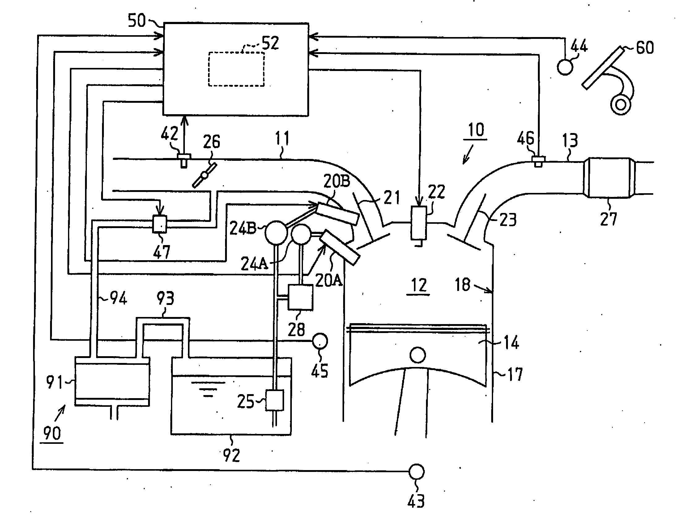
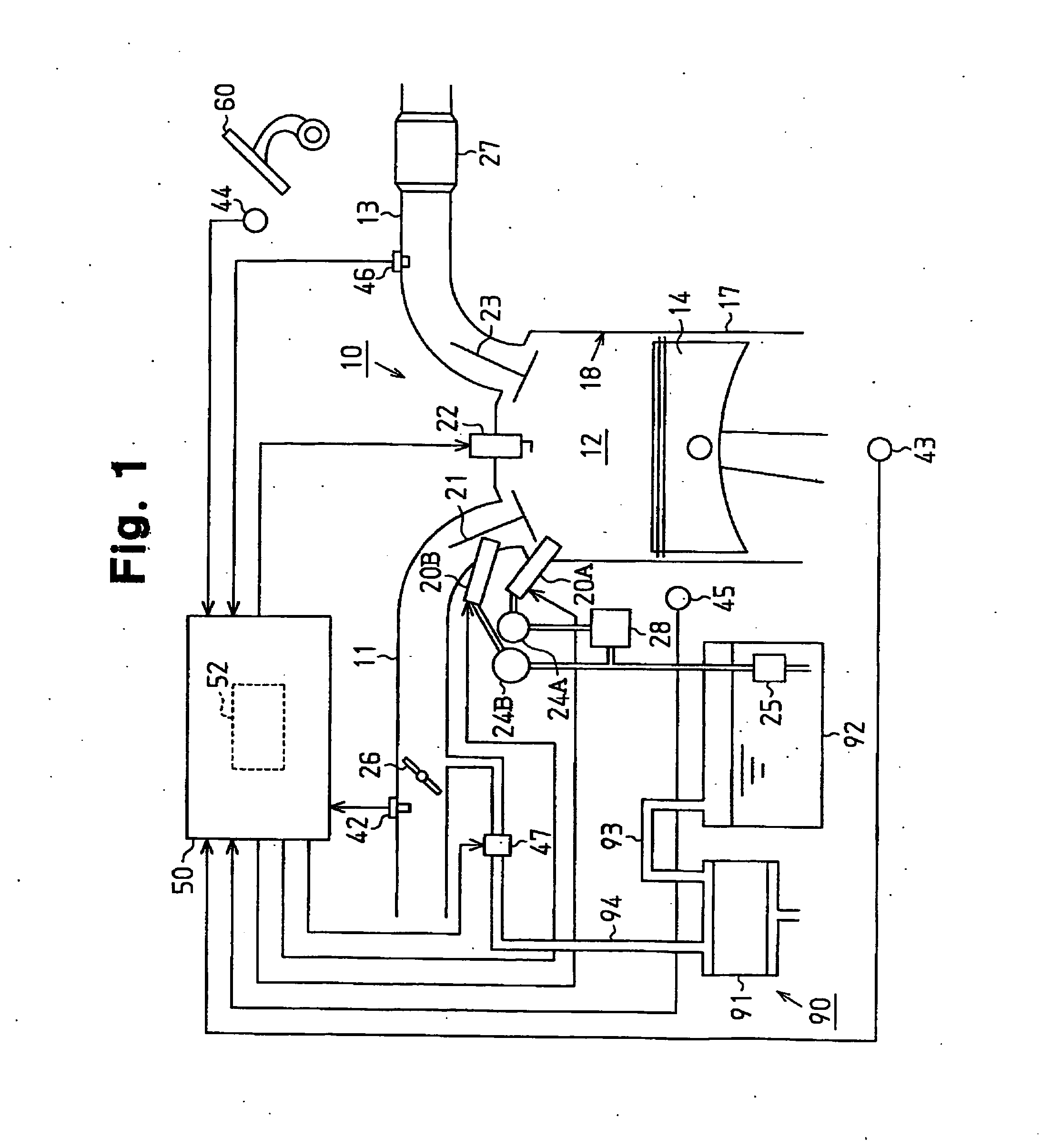
[0017] An internal combustion engine 10 of the first embodiment has cylinders 17 (only one is shown in FIG. 1). As shown in FIG. 1, an engine piston 14 is received and reciprocates in each cylinder 17. A combustion chamber 12 is defined by a top surface of each piston 14 and an inner wall 18 of the corresponding cylinder 17.

[0018] An intake passage 11 and an exhaust passage 13 are connected to the combustion chambers 12. A throttle valve 26 is located in the intake passage 11 and adjusts the amount of the intake air supplied to the combustion chambers 12.

[0019] In the engine 10 of the first embodiment, each cylinder 17 is provided with two injectors, a direct injector 20A for injecting fuel directly into the combustion chamber 12 (in-cylinder fuel injection) and an intake passage injector 20B. The intake passage injector 20B injects fuel into a section of the intake passage 11 downstream fr...

second embodiment

(Second Embodiment)

[0050] In a second embodiment of the present invention, unlike the first embodiment, the in-cylinder fuel injection is prohibited regardless of whether or not the vaporized fuel concentration is unknown, if the purging conditions are satisfied.

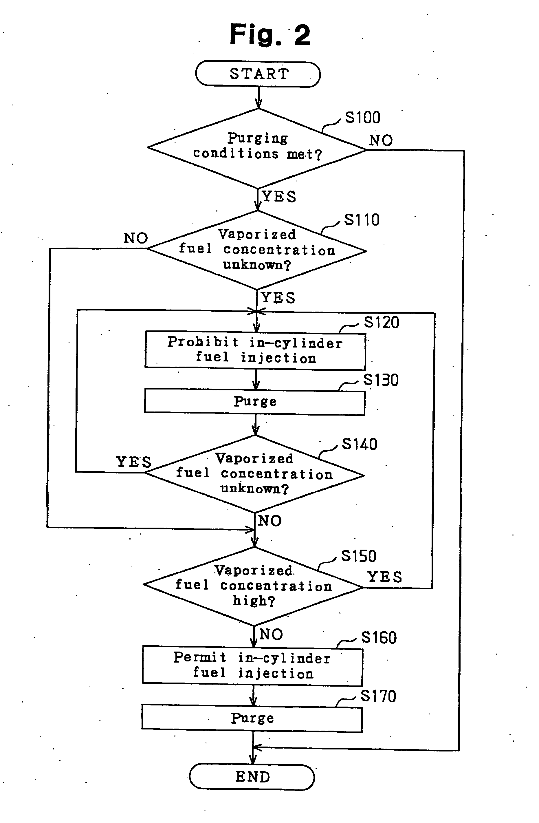
[0051] More specifically, as indicated by the flowchart of FIG. 3, it is determined whether or not the purging conditions are met in step S200. The determination corresponds to that of step S100 of the first embodiment. In the second embodiment, if the determination of step S200 is positive, the procedure proceeds to step S210 and the in-cylinder fuel injection is prohibited. Step S210 corresponds to step S120 of the first embodiment. Thus, if the in-cylinder fuel injection is being performed at this point, the fuel injection amount of the direct injectors 20A is changed to zero, such that the fuel injection amount ratio between the direct injectors 20A and the intake passage injectors 20B is changed. On completion of step ...


PUM


Abstract

An internal combustion engine includes a direct injector for injecting fuel directly into a combustion chamber of the engine, an intake passage injector for injecting fuel into an intake passage of the engine, and a vaporized fuel processing unit for purging purge gas containing a vaporized fuel into the intake passage. A fuel injection control apparatus includes a detecting section and an injection control section. The detecting section detects the amount of the vaporized fuel in the purge gas. The injection control section changes a fuel injection mode of at least one of the direct injector and the intake passage injector depending on the detected amount of the vaporized fuel. As a result, hampering of engine combustion due to purge gas is suppressed.

Description

BACKGROUND OF THE INVENTION [0001] The present invention relates to fuel injection control apparatuses for an internal combustion engine having an injection control section for controlling a fuel injection mode of a direct injector and that of an intake passage injector. [0002] Conventionally, an engine having an intake passage injector for injecting fuel into an intake passage and a direct injector for injecting fuel directly into a combustion chamber is known (for example, refer to Japanese Laid-Open Patent Publication No. 5-231221). In this engine, the air intake efficiency is improved by, for example, performing fuel injection through the intake passage injector while lowering the temperature in the combustion chamber using the heat of vaporization of the fuel injected by the direct injector. [0003] Also, a vaporized fuel processing unit (for example, Japanese Laid-Open Patent Publication No. 10-231758) is known. The unit includes a fuel adsorption mechanism that adsorbs vaporiz...

Claims


Application Information

Patent Timeline
IPC IPC(8): F02D35/00F02D41/00F02D41/02F02D41/04F02D41/30F02D45/00F02M25/08F02M61/14F02M69/04F02M69/46
CPCF02D35/0046F02D41/0045F02D41/3011F02M69/465F02M61/14F02M69/046F02D2041/389F02D41/3094
Inventor YONEZAWA, KOICHI
Owner TOYOTA JIDOSHA KK
Why Eureka
Try Eureka