On/off damper for bikes

Inactive Publication Date: 2005-08-25
CHILL PILL
View PDF7 Cites 4 Cited by
  • Summary
  • Abstract
  • Description
  • Claims
  • Application Information

AI Technical Summary

Benefits of technology

[0006] The primary objective of the present invention is to provide an improved damper which is able to be shut off to adapt to paved roads.

Problems solved by technology

Therefore, the rider may find that whenever a brake is applied, the rider together with the bike will vibrate due to inertia.

Method used


Image

  • On/off damper for bikes
  • On/off damper for bikes
  • On/off damper for bikes

Examples


Embodiment Construction

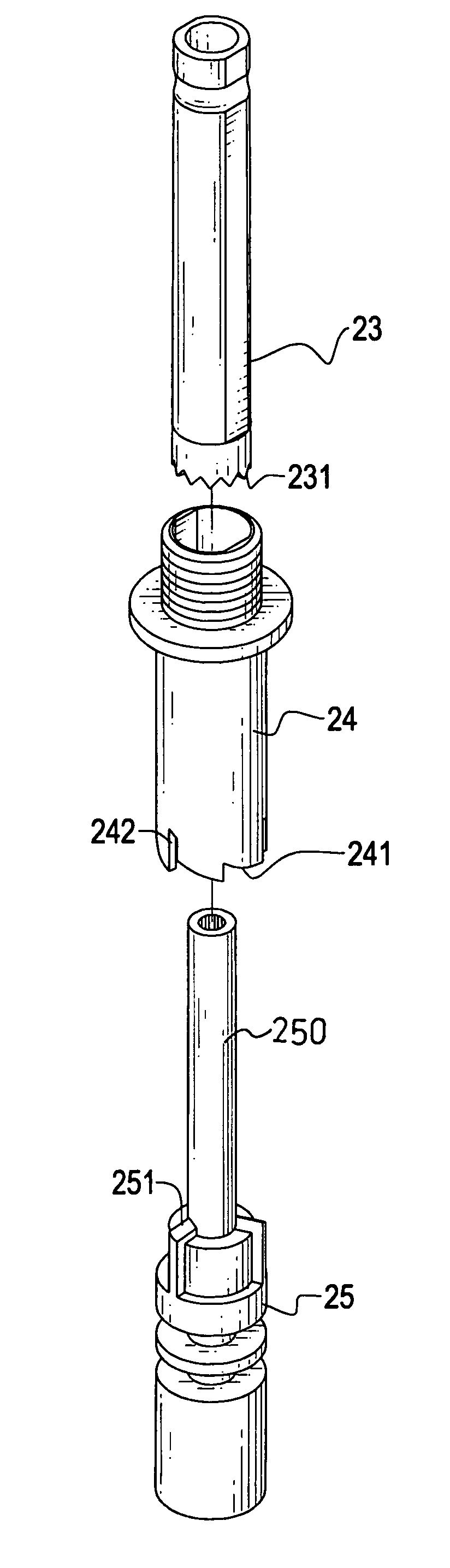
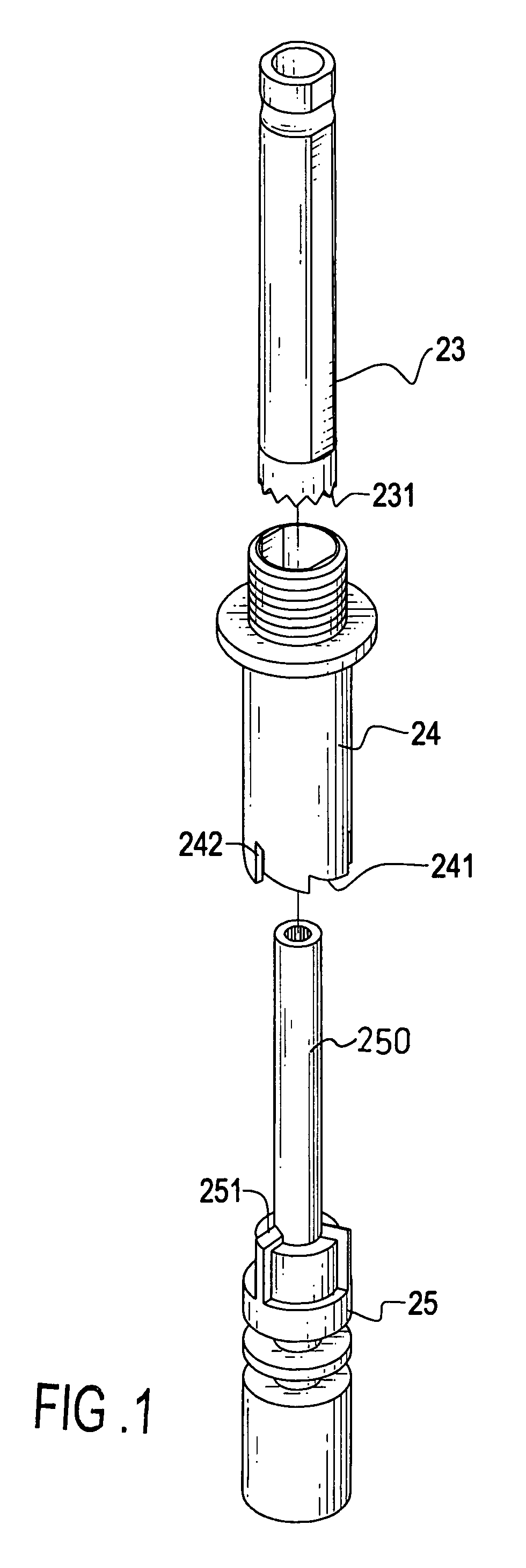
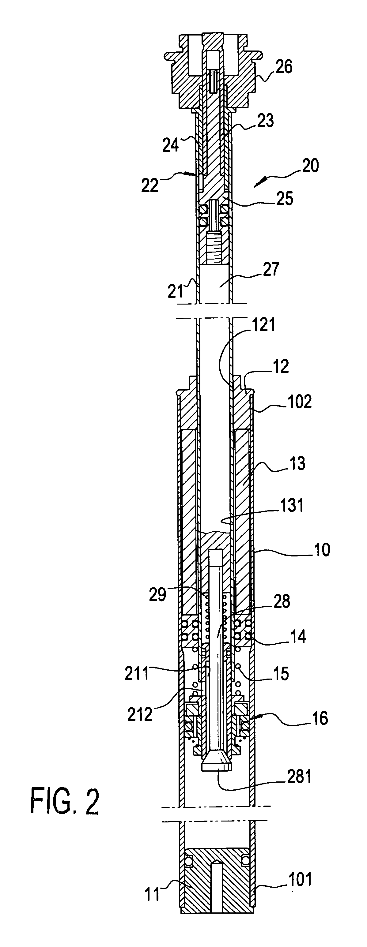
[0015] With reference to FIG. 1 and FIG. 2, an activation device (22) in accordance with the present invention includes an driving tube (23), a stopping tube (24) and a rotating tube (25).

[0016] The driving tube (23) has small slanted teeth (231) formed on a peripheral edge of the driving tube (23). The stopping tube (24) has a configuration so defined that after the driving tube (23) is received in the stopping tube (24), there is no relative rotation between the driving tube (23) and the stopping tube (24). The stopping tube (24) has large slanted teeth (241) formed on a peripheral edge of the stopping tube (24) and having a dimension larger than a dimension of the small slanted teeth (231) and locking grooves (242) formed on the peripheral edge of the stopping tube (24) and having at least one large slanted teeth (241) sandwiched between two adjacent locking grooves (242). The rotating tube (25) has a hollow extension (250) extending upward and into the driving tube (23) and wed...


PUM


Abstract

An activation device for a damper includes a stopping tube adapted to be securely received in the piston rod and having grooves defined in a peripheral edge of the stopping tube and first teeth formed on the peripheral edge of the stopping tube, a driving tube adapted to be movably received in the piston rod and in the stopping tube and having second teeth formed on a peripheral edge of the driving tube and a rotating tube adapted to be movably received in the piston rod and having third teeth engaged with the second teeth so that the movement of the driving tube is able to drive the rotating tube to rotate an angle to selectively allow a corresponding one of the third teeth to be received in the grooves such that communication between the axial passage and the space is selectively plugged.

Description

BACKGROUND OF THE INVENTION [0001] 1. Field of the Invention [0002] The present invention relates to a damper, and more particularly to a damper which is able to be deactivated and activated according to the road conditions. [0003] 2. Description of Related Art [0004] Conventional bike dampers constantly provide damping effect to the bumpy road conditions such that the rider is able to enjoy the fun of riding. When the rider is riding across the country or passing a mountainous area, the rider requires large damping effect to damp the impact from the roads. When the rider is passing a metropolitan area where the roads are nicely paved, the rider generally does not require that much damping effect. However, the same damping effect will be provided to the rider despite the road conditions are changed. Therefore, the rider may find that whenever a brake is applied, the rider together with the bike will vibrate due to inertia. Some may find it amusing but it does affect the rider's enjo...

Claims


Application Information

Patent Timeline
IPC IPC(8): B62K21/00B62K25/04B62K25/06B62K25/08F16F9/32F16F9/44F16F9/56
CPCB62K25/04B62K25/06B62K25/08F16F2232/04F16F9/44F16F9/56B62K2025/047
Inventor TSAI, CHIN-SUNG
Owner CHILL PILL
Why Eureka
Try Eureka