Screen

a screen and screen technology, applied in the field of screens, can solve the problems of leakage at the screen, low obtainable throughput, and high maintenance cost of screens, and achieve the effect of high separation accuracy and easy manufacturing

Inactive Publication Date: 2005-08-25
ANDRITZ AG
View PDF7 Cites 0 Cited by
  • Summary
  • Abstract
  • Description
  • Claims
  • Application Information

AI Technical Summary

Benefits of technology

[0010] The screen according to the invention in the above or one of the other embodiments described below has the following advantages:
[0036] When the screen is used as a washer, efficient fractionation of the suspension feed to the screen into organic and inorganic suspension components can be achieved by selecting the correct impact angle, profiling, shape of bars (for bar-type screens), and curve of the screen surface. If sufficient wash water is added to the reject flows, which contain a higher proportion of fibers, the screen can be used as a single-stage or multi-stage washer.

Problems solved by technology

The disadvantage of these known screens is that rotors are essential as a cleaning device to keep the screen slots clear, and these moving parts are susceptible to faults, consume substantial amounts of driving energy, and also frequently lead to problems with leaks at the screen.
Furthermore, these screens require a relatively high level of maintenance and are thus expensive to run.
The screen surfaces are small, thus the obtainable throughput is low.
The disadvantages of this kind of screen lie in the high energy consumption required to generate the pressure impulses, substantial demands on the suspension pump, and undesirable transmission of the pressure impulses beyond the screen and into other plant components.
Their screening efficiency and their throughput are very low, which is why this type of vibration screen is rarely still in use except as a so-called final stage screen.

Method used


Image

  • Screen
  • Screen
  • Screen

Examples


Embodiment Construction

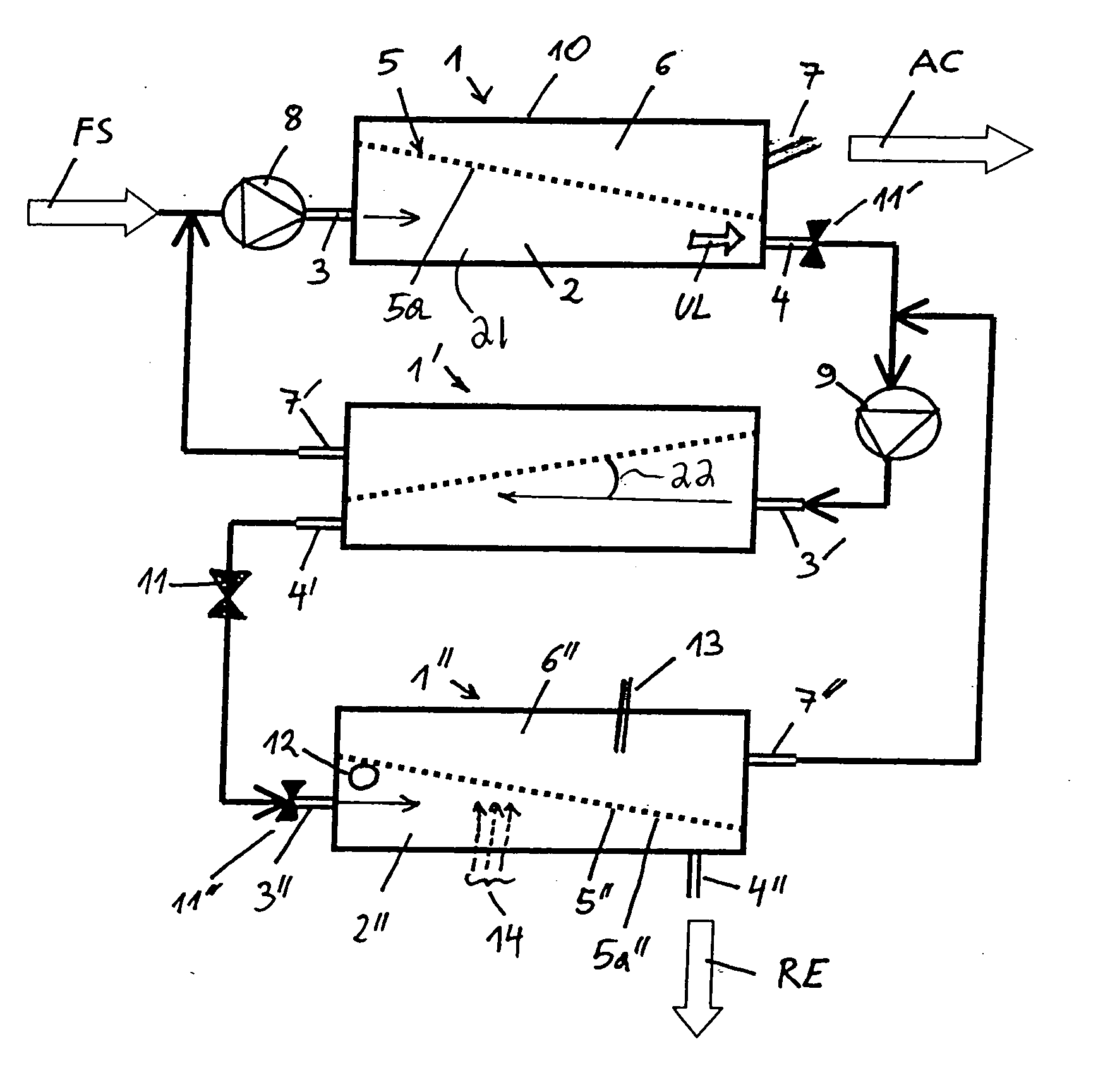
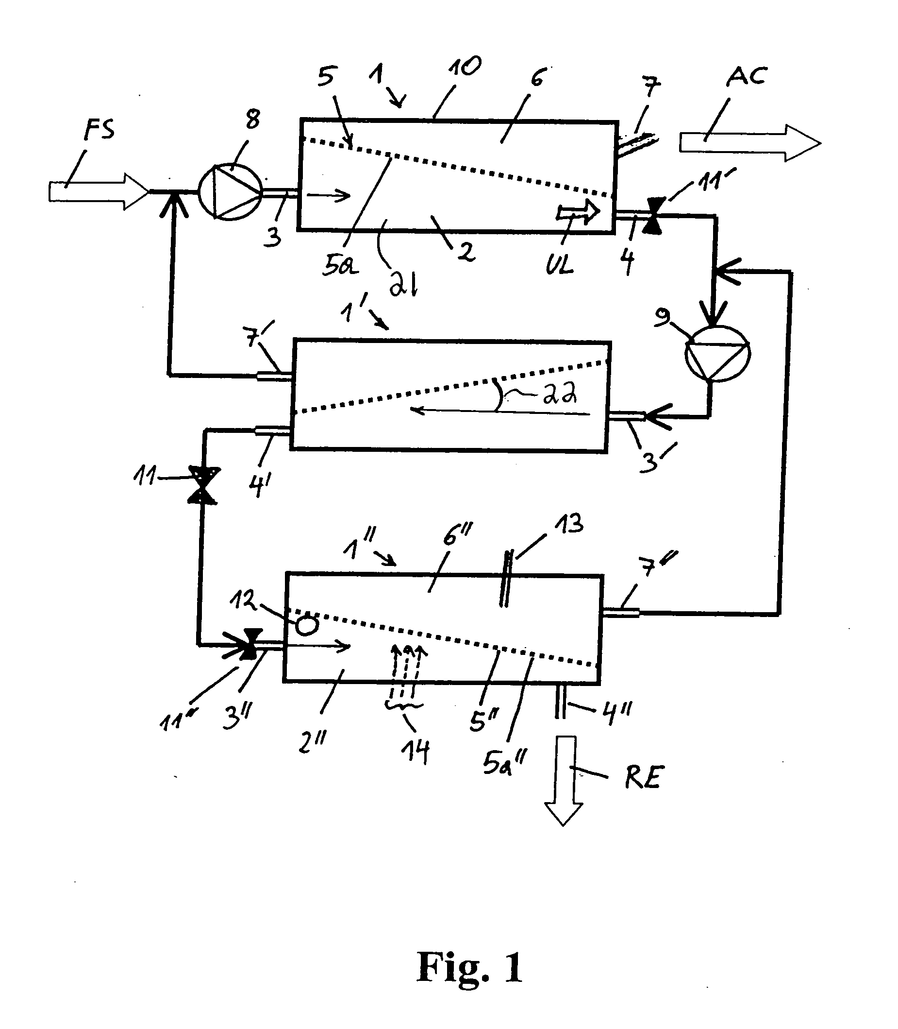
[0043]FIG. 1 shows a 3-stage screening unit for cleaning a pulp suspension with the screens 1, 1′, 1″ according to the invention, mounted in series. The three screens are of similar design, which will be described in more detail on the basis of screen 1. The screen 1 for cleaning a pulp suspension FS has a separation chamber 2, defined by a housing 10, with a pulp suspension feed 3 and a reject outlet 4. A pulp suspension FS is conveyed by a pump 8 through the pulp suspension feed 3 into the separation chamber 2. In the separation chamber 2, an accept chamber 6 with an accept outlet 7 pointing upwards is separated from the pulp suspension feed 3 and the reject outlet 4 by a dividing wall 5 with a screen structure 5a. The dividing wall 5 divides the separation chamber 2 asymmetrically into an accept chamber 6 and a suspension chamber 21. The pulp suspension flows onto the screen structure 5a at high speed, where part of the suspension is pressed through the screen structure 5a and is...


PUM

PropertyMeasurementUnit
step heightaaaaaaaaaa
flow angleaaaaaaaaaa

Abstract

A screen for cleaning a pulp suspension includes a housing forming a separation chamber. The housing includes a pulp suspension feed, a reject outlet and an accept outlet. A dividing wall disposed within the housing divides the separation chamber into a suspension chamber and an accept chamber, with the pulp suspension feed and the reject outlet being in fluid communication with the suspension chamber and the accept outlet being in fluid communication with the accept chamber. The dividing wall includes a screen structure having a suspension side adjacent the suspension chamber and an oppositely disposed accept side adjacent the accept chamber. At least the suspension side of the screen structure has profiling for generating turbulence in the pulp suspension flowing against the screen structure to create a self-cleaning effect in the screen structure.

Description

BACKGROUND OF THE INVENTION [0001] This invention relates generally to screens. More particularly, the present invention relates to screens for cleaning a pulp suspension. [0002] Screens are machines that are used in the paper industry to clean a pulp suspension consisting of water, fibers, and dirt particles. Here, a pulp flow is fed through a screening device, where the accept flow, comprising water and fibers, flows through the screen. A partial flow, known as the reject flow and consisting of water, fibers, and dirt particles, is generally removed at the end opposite the feed flow. Thus, the screens fractionate solids particles suspended in water. By contrast, filtration processes separate the liquid from the solids. [0003] In general, a screen of this type has an axially symmetrical design and comprises a housing with a pulp feed, a cylindrical screen basket, usually with perforations or vertical slots, and a rotating rotor. The rotor is responsible for keeping the screen slots...

Claims


Application Information

Patent Timeline
Patent Type & Authority Applications(United States)
IPC IPC(8): D21D5/02D21D5/04
CPCD21D5/04D21D5/02
Inventor GABL, HELMUTH
Owner ANDRITZ AG
Why Eureka
Try Eureka