Laser welded butterfly valve blade

a butterfly valve and blade technology, applied in the field of blades of butterfly valves, can solve the problems of incorrect air/fuel mixture, loose fasteners, and complicated assembly of openings and fasteners,

Inactive Publication Date: 2005-08-25
SIEMENS VDO AUTOMOTIVE CORP
View PDF13 Cites 17 Cited by
  • Summary
  • Abstract
  • Description
  • Claims
  • Application Information

AI Technical Summary

Benefits of technology

[0008] The butterfly valve blade is fixed to the shaft to prevent relative movement between the shaft and the butterfly valve blade. The shaft or the butterfly valve blade includes a plastic portion composed of a laser absorbent material. The other of the butterfly valve blade and shaft includes a portion formed of a laser transparent plastic material. The butterfly valve blade and the shaft include mating geometric features that provide a desired fit between the shaft and the butterfly valve blade to aid in the welding operation.

Problems solved by technology

The openings and the fasteners complicate assembly.
Disadvantageously, fasteners can come loose and fall into the air passage.
Further, a loose butterfly valve blade may allow rotation relative to the shaft, causing an incorrect air / fuel mixture.
Disadvantageously, assembly of the shaft and butterfly valve blade may require some adjustment that is not provided by the rigid connection.
This is compensated for by decreasing part and assembly tolerances that can result in increased costs.

Method used


Image

  • Laser welded butterfly valve blade
  • Laser welded butterfly valve blade
  • Laser welded butterfly valve blade

Examples


Embodiment Construction

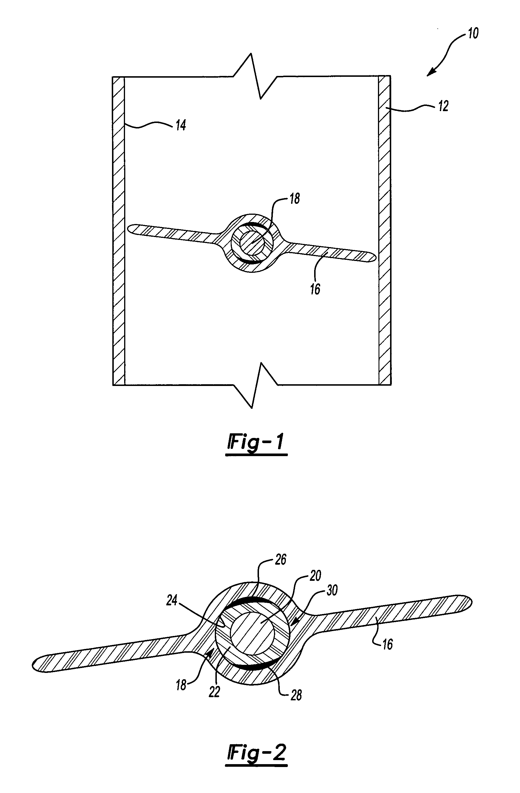
[0018] Referring to FIG. 1 a butterfly valve assembly 10 includes a body 12 defining an air passage 14 and a butterfly valve blade 16. A shaft 18 supports the butterfly valve blade 16 and rotates to selectively block airflow through the air passage 14. The butterfly valve blade 16 is fixed to the shaft 18 to prevent relative movement between the shaft 18 and the butterfly valve blade 16.

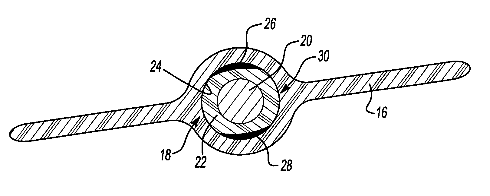
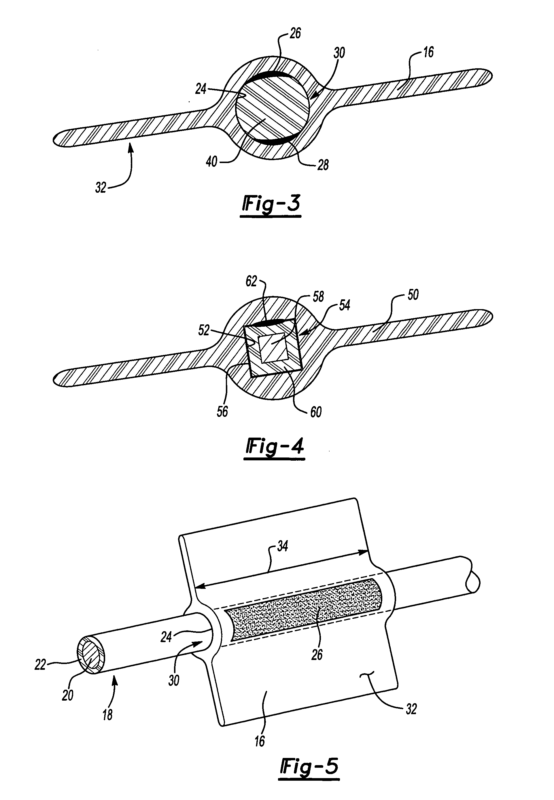
[0019] Referring to FIG. 2, the shaft 18 includes a metal portion 20 and a plastic portion 22. The example butterfly valve blade 16 is formed of a plastic material that is substantially transparent to a laser. A laser transparent plastic material allows enough laser energy to be transmitted though the material for welding. The plastic portion 22 of the shaft 18 is a formed from a material that absorbs energy from the laser and converts that energy into heat in a localized area. The heating of the localized area results in melting of the material to form the desired weld. The butterfly valve blade in...


PUM

PropertyMeasurementUnit
transparentaaaaaaaaaa
laser transparentaaaaaaaaaa
energyaaaaaaaaaa

Abstract

A butterfly valve blade (16) is attached to a shaft (18) by a laser weld between an inner surface (24) of the butterfly valve blade (16) and the shaft (18). The shaft (18) includes a plastic portion (22) composed of a laser absorbent material. The butterfly valve blade (16) is formed of a laser transparent plastic material. A laser is directed through the butterfly valve blade (16) onto the plastic portion (22) of the shaft (18). Energy form the laser heats the laser absorbent material of the shaft (18) that melts in the presence of the laser. The butterfly valve blade (16) is heated by the heated shaft (18) to melt and form the desired weld that secures the butterfly valve blade (16) to the shaft (18).

Description

BACKGROUND OF THE INVENTION [0001] The application claims priority to U.S. Provisional Application No. 60 / 547,688 that was filed on Feb. 25, 2004.[0002] This invention relates generally to a butterfly valve blade. More particularly, this invention relates to plastic butterfly valve blade attachable to a rotating shaft. [0003] A butterfly valve assembly is utilized to meter airflow through an air passage. One example is a throttle body assembly that utilizes a butterfly valve to meter airflow corresponding with fuel from a fuel injector to provide a desired air / fuel mixture. The butterfly valve blade is commonly attached to a shaft that is rotated to rotate the butterfly valve and thereby vary an opening for airflow. [0004] The butterfly valve blade is typically attached to the shaft by way of fasteners such as screws or rivets. Such fasteners require corresponding openings in the butterfly valve blade and in the shaft. The openings and the fasteners complicate assembly. Disadvantage...

Claims


Application Information

Patent Timeline
Patent Type & Authority Applications(United States)
IPC IPC(8): B23K26/32B23K31/02B29C65/02B29C65/16F16K1/22
CPCB23K26/3206B23K31/02B29C65/1635B29C66/21B29L2031/7506Y10T29/49405B29C66/1122B29C66/52272B29C66/53241B29C65/1677B29C65/1683F16K1/221B23K26/32B29C66/7392B29C66/73921B23K2103/50
Inventor NARAYANASWAMY, KARTHIKEYAN R.HARVEY, BRUCE J.
Owner SIEMENS VDO AUTOMOTIVE CORP
Why Eureka
Try Eureka