

Do-it-yourself system for portable generator
- Summary
- Abstract
- Description
- Claims
- Application Information
AI Technical Summary
Benefits of technology
Problems solved by technology
Method used
Image

Examples
Embodiment Construction
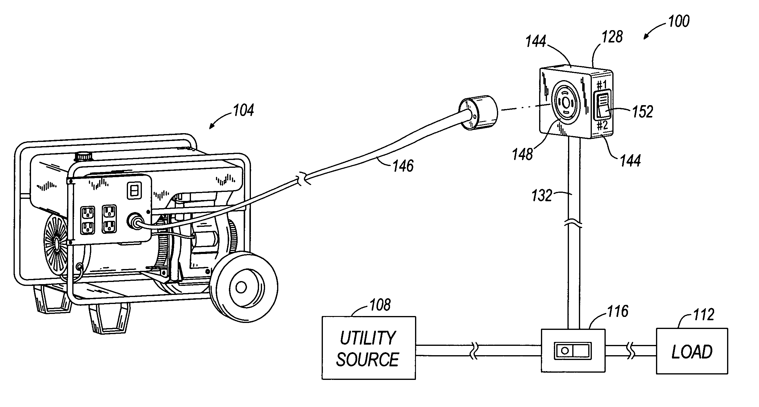
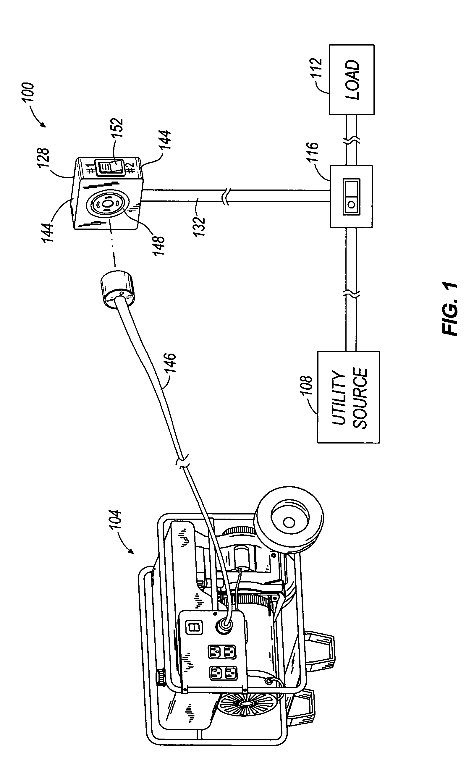
[0013]FIG. 1 shows a do-it-yourself (“DIY”) system 100 for portable generators. The DIY system 100 connects power, either from a generator 104 or from a utility source 108 to a hard-wired residential load 112. The load 112 is generally connected in circuit to a load power switch 116 that switches power to the load 112. In other embodiments, the load power switch 116 may be integrated with the load 112.
[0014] Typical hard-wired residential loads include furnaces, air conditioning units, and the like. When the load power switch 116 is in an ON position, the load power switch 116 connects a selected power to the load 112. When the load power switch 116 is in an OFF position, the load 112 is disconnected from any power source. In an alternative embodiment, when the load power switch 116 is in the OFF position, the load 112 can be disconnected from the utility power source 108, but connected to the generator 104, detailed hereinafter. In the embodiment shown, the load power switch 116 c...
PUM
 Abstract
Description
Claims
Application Information